TL431 is a cheap ‘n’ cheerful yet reliable programmable precision shunt regulator chip available in 3-pin TO-92 package. This monolithic IC voltage reference operates as a low temperature coefficient zener which is programmable from Vref to 36 V with only two external resistors.
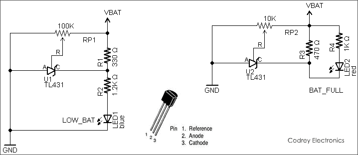
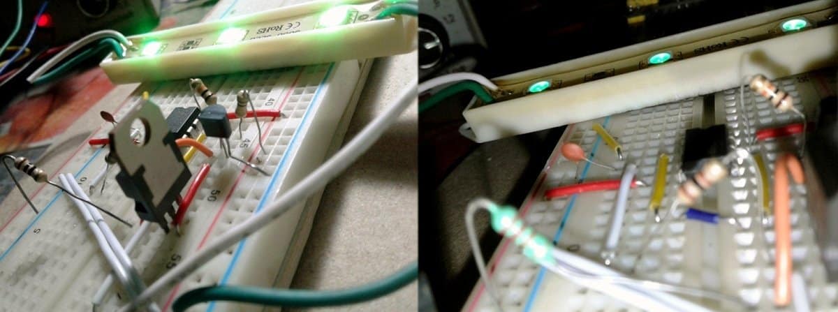
In this article, you can find two simple circuits built around the nifty TL431 chip, designed as add-ons for 1S lithium-Ion (Li-Ion) battery circuits. The circuit at the left side in the image shown below is a low-battery indicator while the right side one is a battery-full indicator. First of all, note that the nominal voltage of today’s single-cell (1S) Li-Ion battery is 3.7V whereas its maximum voltage is around 4.2V, and discharging below 2.8V will kill the battery sooner or later!
Both circuits can be connected in parallel with any 1S Li-Ion battery. However, you should calibrate them before the initial use as indicated below:
- Low-Battery Indicator: Connect the circuit to a lab power supply with correct polarity (VBAT=+ & GND = GND) and adjust the trimpot (RP1) so that its wiper (connected to the reference terminal of the chip) is at 2.5 V when the dc input is 3V. Check that the blue indicator lights up at this stage
- Battery-Full Indicator: Connect the circuit to the lab power supply with correct polarity (VBAT=+ & GND = GND) and adjust the trimpot (RP2) so that its wiper is at 2.5 V when the dc input is 4.2V. Check that the red indicator lights up at this stage
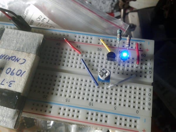
After calibration, ensure that the blue indicator in the low-battery indicator lights up when the battery voltage is at 3.0V (or falls below 2.9V), and the red indicator wakes up when the battery voltage reaches at 4.2V (or goes above 4.1V). Low-current (2-5mA) type 3mm blue/red LEDs are preferred for these circuits. Similarly, multi-turn trimpots are good here for better precision.
I hope that you leave learned something new and have fun with this idea. Very best regards from T.K !
Very easy, economical and useful circuit.
Thanks!
That was really great and most important for li-ion battery,sir can u make a low cut off for 18650 battery and i have a so many of them. Their is no other circuits in google. Anyway that was great
Glad to know you like my project idea. Thanks! Your suggestion is noted, and sure I’ll come up with such a circuit within a couple of weeks. Please stay tuned!
Battery low indicator is ok but where is the battery full indicator
(Is that working or not) please reply me sir its very important for me..
Refer the schematic again.The circuit at the left side is a low-battery indicator while the right side one is a battery-full indicator.
can i use this circuit during the charging the battery?
Amin: You may try that, but there’s some risk that you end up messing with the charge cycle. If you have a system with charger and battery joined together, then it’d be better to use an additional switching circuit to turn the indicator circuit ‘on’ only when the charging input is absent. Hope this helps!
Hello! Thanks for sharing your circuits!
Can you gibe me the values for the resistors for a 2S-circuit, please? I don’t understand the datasheet 🙂
Thank you!
RBX: See the quick note on trimpot adjustment procedures:
1: For a 2S LiPo, suggested threshold level for the “LOW_BAT” indicator is 6.4V. So, connect the same circuit to a variable dc power supply and adjust the trimpot RP1 so that its wiper (connected to the reference terminal of the chip) can then see 2.5 V when the dc input is 6.4V (Blue indicator lights up at this time). Not very necessary but you can change R1 value to 470 Ohm.
2: For the “BAT_FULL” circuit, the suggested threshold voltage is 8.4V. So, connect a variable dc power supply and adjust the trimpot (RP2) so that its wiper can see 2.5 V when the dc input is 8.4V (Red indicator lights up). Again, not very necessary, but you can change the value of R3 to 560 0r 680 Ohm, and R4 to 1.2K or 2.2K Ohm.
Hope this helps. Do these modifications and let me know. Good luck!
Thank you for your reply!
I will test it when my variable dc power supply arrives the next few days 🙂
Hello!
It works! Thank you!
RBX: Glad to hear. Thanks!