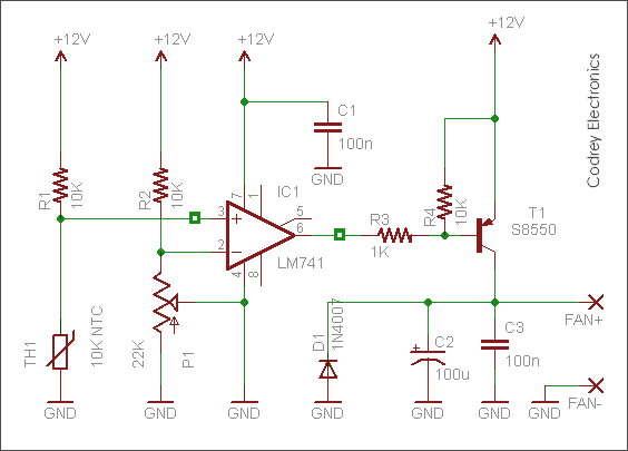
Active heat sink fan controller presented here is a very simple yet highly useful circuit for automatic control of cooling fans in active heat sink units. The circuit is realized using easy-to-use inexpensive parts and the design is centered around a standard 10K NTC thermistor. See the tried and tested circuit diagram of the 12V cooling fan controller shown below:
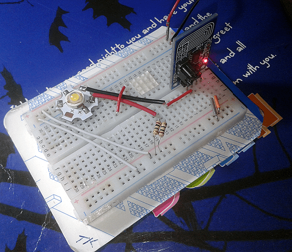
The cooling fan you see in the below picture (reference image) has the thermistor at the end of a twin-wire cable tied to the cooling fan frame. When the cooling fan is installed on the rest of the heat sink this thermistor should mounted in between two of the copper fins, or between the copper fin and the aluminum frame of the heat sink assembly as necessitated. In this way, the
thermistor stays in direct contact with the metal part and hence able to sense temperature changes effectively.

For Calibration, you will need a digital thermometer whose accuracy you trust. Start by setting the trimpot (P1) wiper to roughly its mechanical center position. Next, bring the thermistor to the temperature you want to use as the minimum (say 40 degree centigrade), then adjust the trimpot so that the circuit drives the cooling fan at that point. Note that, to make it less sensitive to minute disturbances, add a suitable trimpot (500K for instance) between pin 6 and pin 3 of IC1 to set the hysteresis. Adjusting this ‘hysteresis’ trimpot might throw off the set point slightly, so be sure to recheck your calibration before real-world use.
Also remember, the maximum current available to power the cooling fan is dictated by the ‘Ic’ rating of the driver transistor (T1) chosen. Consult datasheets for your intended cooling fan and transistor. The S8550 used here will handle current close to 700mA.
A bit of maths
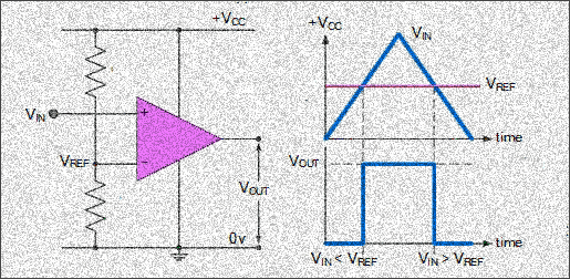
Here, a varying input voltage is compared with a fixed reference voltage by IC1. If the input voltage is higher than the reference voltage, then the output is positive. If the input voltage is lower than the reference voltage, then IC1 output is negative. Suppose that you fix the trimpot at 8K, and the resistance of the thermistor is 10K (at 25 degree C), then according to the potential divider rule reference voltage (vref) is 5.3V, and the input voltage (Vin) is 6.0V. Since Vin is higher than Vref, output is positive, and T1 remains in off state. Now think that temperature increases and resistance of the thermistor decreases to 6K (just above 35 degree C). This results in a Vin of about 4.5V, lower than the Vref level to gives a negative output to turn on the fan driver transistor T1.
To keep things simple, just note that when Vin is greater than Vref, output will saturate towards the positive supply rail. When Vin is less than Vref output will change state and saturate at the negative supply rail. The above calculation can be used as a helpful reference to understand/ tweak the operation of the cooling fan controller.
If you look carefully you will notice that the given circuit is somewhat different from many other published circuits. Yes, actually I designed this non-inverting comparator as a part of an
electronic cooling thermostat (not a fan controller) in my Peltier Fridge project (more on later). Anyway, you are free to start your own experiments by swapping the inputs of IC1, changing the type of driver transistor, replacing the output load (cooling fan) with an electromagnetic relay, etc.

Thank you sir for this wonderful artiticle. i would like to ask. please is this circuit tested and work well?
@Solomon: You’re welcome. It’ll work. Feel free to make remarks and also make proposals for the following articles. Thank you!