Certainly, I’m not going to share something about constructing your own strobe for use in discotheques. Let me make little headway against the topic – LED strobes!
Strobing?
Yes, Strobing! Note that with the help of a strobe it’s not only easy to measure the speed of rotating machinery but also it’s possible to freeze down the rotation effectively for close visual inspection. In order to strobe a rotating machinery just set the strobe to flash at a rate of once per revolution. If so the rotation will appear to stop because the machine will be in the same position each time the strobe flashes. In addition, if the strobe flashes slightly faster then the machine will appear to rotate slowly backwards, and if the strobe flashes at a slightly slower rate, then the machine will appear to rotate slowly forward. Too improbable to admit? Okay, I’ll try to prove it by means of a crude experiment.
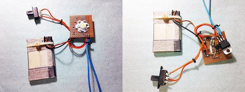
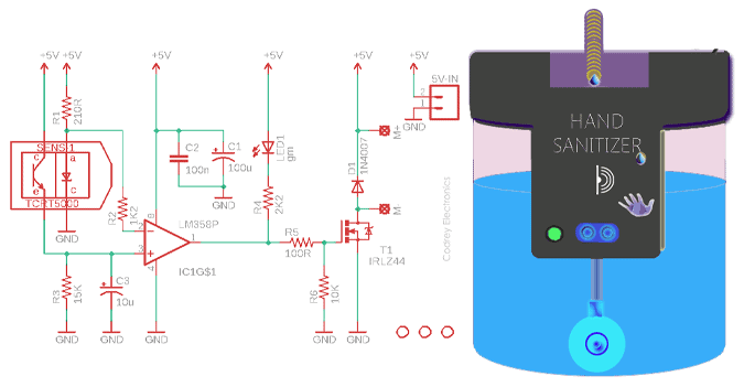
If you refer back to the previous cooling fan articles published by me, it can be seen that a standard 3-wire cooling fan provides a ‘tacho’ signal output through its third wire to share the speed information. Usually, the tacho output is an open-collector type (external pull-up resistor required) output that exactly delivers two pulses per rotation. Obviously we’re going to try a simple trick with a similar but 5VDC rated 3-wire cooling fan. So do follow the schematic shown below to prepare your setup.
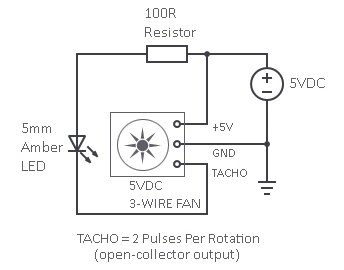
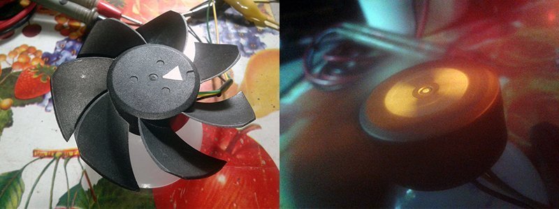
Thereafter, firmly stick a piece of reflective white tape on the hub of the fan, and power up your setup through a regulated 5VDC power supply. Then shine the LED on the sticker and check the result. In all likelihood, especially if it’s in a dark corner, you can see two reflections on the ‘frozen’ fan hub.
Well, we just learned that if the sticker is illuminated with a light flashing at the same frequency as the hub rotation, the sticker will appear to ‘static’ due to the stroboscopic effect. But here the strobe frequency is twice and hence we can see it in twofold (180 degree apart). The room has to be pretty dark for the amber light source/strobe to be the primary illumination, so I did it with the lab lights off (sorry for the blurred snap).
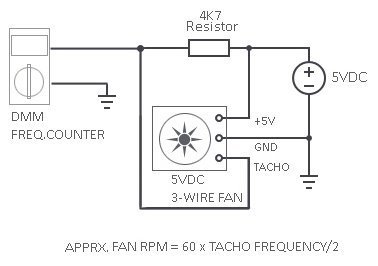
Nevertheless, many digital multimeters (DMMs) have a frequency counter mode on them. If you owned such a DMM and want to measure the RPM of a 3-wire fan, there’s no need for a strobe setup because you can easily measure the tacho frequency with a bare setup(see below) to get the approximate fan RPM.
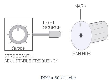
However, incase of a 2-wire fan (the common fan), you will need to pick an external LED strobe that can generate strobe of changeable frequencies (more follows). If so, when the mark (reflective tape) is stationary, the LED strobe is flashing at the same frequency as the fan is rotating. If the strobe frequency is known, the rotational speed is also known, and can be calculated in RPM.
Oh, I missed that remark – In the electronics world, the slang “strobe” simply denotes a device that provides a flashing light synchronized with the periodic movement of an object (to make moving objects appear standstill).
Wagon Wheel Effect?
Wagon Wheel effect is a phenomenon in which a spinning wheel might appear to be stationary under a strobe light. The reason why this happens is that the rotational frequency of the spinning wheel is an integral multiple of the strobe frequency. So, every time the strobe light flashes, the wheel comes to the same position as before, makes the wheel appears stationary.
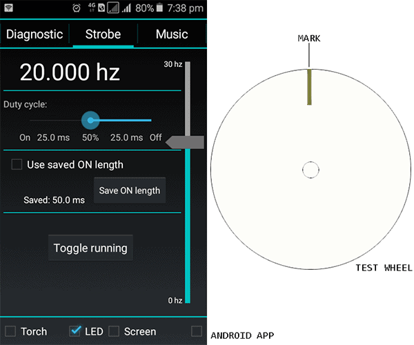
You’ll only need a strobe light app (Android/iOS) and a spinning wheel for a funny play with the Wagon Wheel effect. Keep the test space as dark as possible, and set your spinning wheel to motion. Turn on the strobe light and start with a high strobe frequency and gradually lower the frequency until you see the spinning wheel become stationary. Get me?
In my case, I used the “Strobily” app downloaded from Google Play. My test wheel appears stationary at a frequency of 11Hz. As I pointed before, the spinning wheel appears stationary only when the frequencies match. So, the frequency of the strobe light is the rotational frequency of the test wheel. So, I can say that my test wheel makes 11 revolutions per second, resulted in 660RPM.
Stroboscopic Tachometer?
Now it’s clear! If you can drive a bright light source – preferably one light-emitting diode – through an oscillator made to generate a pulse wave of known frequency, you can reasonably measure the rotational speed of an object with that clever setup. Are you going to make an LED Stroboscope (or the LED Strobe) yourself? Great! My thoughts on how to build a cheap and cheerful LED Strobe can be found at the following segments.
The underlying idea is simple – at first rig up an adjustable oscillator to generate a pulse wave of known frequency that can then used to drive an ultra-bright white LED. Next, make a reflecting mark on the object that’s rotating that you want to measure, and spin the object up to the speed. Set the oscillator at a lower frequency to start with, and show the LED at the object where the mark is. Initially, the mark will appear at random points around the object but don’t worry, try gradually raising the oscillator frequency until the mark appears to remain stationary. When the mark is stationary, the LED is flashing at the same frequency as the object is rotating. As pointed earlier, if the oscillator frequency (strobe frequency) is slightly lower than the speed of the object, the mark will appear to rotate forward, and if the strobe frequency is slightly higher than the speed of the object, the mark will creep backwards. One thing you also have to take into serious consideration is the duration of the strobe i.e. when using a strobe, the flash duration should be as short as possible to prevent blurring of the strobed mark/image.
Anyway, I’ve a dispute with the aforesaid frequency selection procedure especially when it comes to the measurement of a machine’s rotational speed by a stroboscopic tachometer. For better results, while using a stroboscopic tachometer you should begin the measurement from the highest frequency that’s possible, and then reduce the strobe frequency gradually as needed. Why it’s said that you’ve to set it to the highest level at which the machine appears to stop? Note that the same effect may also occur if strobing takes place at 1/2 speed or 1/3 speed or 1/4 speed…!
Therefore, always start the stroboscopic tachometer with a higher strobe frequency and then lower it. Follow this good practice at all times if you don’t want other integral multiples of the frequency to match up with the spinning object (if anything is unclear, be sure to drop me a message).
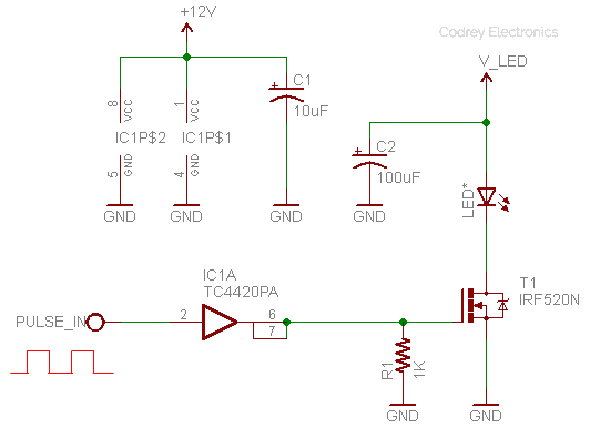
Back to the stroboscopic tachometer build project, one 0-100Hz adjustable frequency generator circuitry (preferably with an accuracy of 0.01Hz which is very useful for fine-tuning when you’re close to the goal) will be a good pick here for measuring RPM up to 6000. For the light source, you can use any high-power white or blue LED – the latter is my choice. Before going to build the final oscillator circuitry, it’s good to make the power LED driver at first, as you can use it through a function generator to test and verify the concept once again. So, next is the basic version of the power LED driver circuit.
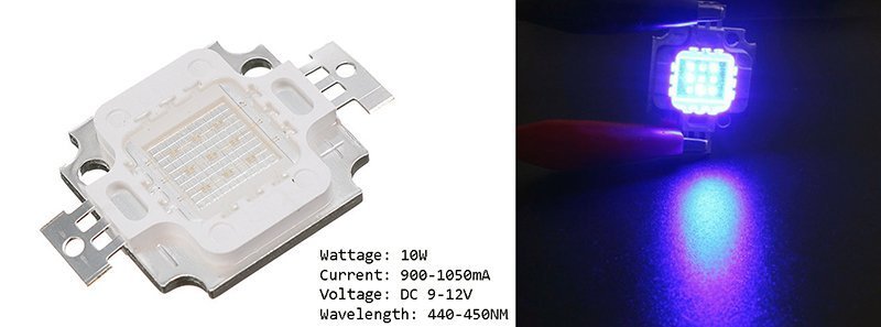
This is the 10W blue LED used in my experiments – a pretty nice $3 gem from Banggood!
In the next (concluding) part of this article, I’ll show you the final adjustable oscillator scheme tailored for the do it yourself stroboscopic tachometer project. As a bonus, you’ll get an Arduino based stroboscopic tachometer, too. Anyway, keep in mind, we can’t do that with the ‘traditional’ Arduino PWM method, because it generates a constant frequency (~488 Hz) and varies the duty cycle. We need a variable frequency with a constant pulse length. Okay, see you next time!
Useful Links
- Wagon Wheel Effect https://en.wikipedia.org/wiki/Wagon-wheel_effect
- TC4420 Datasheet https://ww1.microchip.com/downloads/en/DeviceDoc/21419D.pdf
- IRF520 Datasheet https://www.vishay.com/docs/91017/91017.pdf
- Strobily https://play.google.com/store/apps/details?id=com.tp77.StrobeAd&hl=en_IN
- DIY Function Generator Project http://www.technoblogy.com/show?20W6
Dear sir kindly publish the LED Strobe Primer – Part 2, we are very eager to waiting thank you
ASHOKKUMAR: I completely forgot about the project. Thanks for reminding!
The 2nd part of this project will be available for readers by January 2021 after it completes the final stage of lab trials. Stay tuned…
Dear sir kindly publish stroboscope project part 2 , we are waiting for that for past 3 months.Thank you.
ASHOKKUMAR: Thanks for your patience. It’s almost ready, and sure you can see it here in March 2021. Delays in project construction are due to parts being sent too slowly by vendors (impact of the corona). Hope you understand!
Dear sir kindly publish stroboscope project sir.Thank you