It’s rather ridiculous to think how cheap you can get light sensor modules today. Sure, you’ll get those by online for a couple of coins!
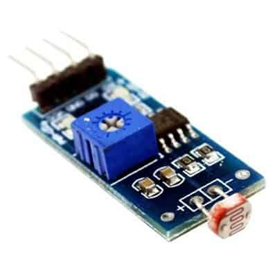
Most Chinese light sensor modules have a photo resistor or a phototransistor as the light sensor that’s combined with one basic comparator circuitry to give a logic-level on/off output signal. You can simply ‘walk’ into any online store, get a Cheapo light senor module and are all set. Anyway, that’s not the clever choice, and the choice has some serious shortfalls that limit your application ideas vastly. For the very first time, however, I’d recommend to try a discrete electronics circuit for that yourself, might be a bit harder, but at least you’ll know what’s you’re doing!
Ready to read and learn? Well naturally I’m going to take quick digression, but that’s obviously to give you some ideas on how to build a photoelectric light sensor and what to do with it. Okay, let’s get started!
Some words up front: The rest of this post will go through a couple of thoughts on constructing simple photoelectric light sensors. For the start, you’re going to need a photodiode as the key component. See, the SFH 213 is a quite popular photodiode (Silicon PIN Photodiode with very short switching time) from Osram (http://www.farnell.com/datasheets/1672048.pdf).
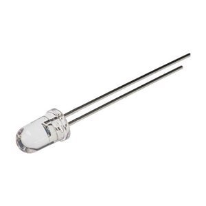
It’s worthful to notice that the prime difference between a photodiode and a phototransistor is that the photodiode uses p-n junction diode which converts the light energy into an electric current, whereas the phototransistor uses an ordinary transistor for the conversion of light into current. The photodiode comprises the normal p-n junction (which generates an electric current when light is incident on its active surface) is housed inside a transparent shell through which light can enter inside. Although both the photodiode and phototransistor work on the principle of the inner photoelectric effect, the sensitivity of a standard photodiode is very much lower than that of a phototransistor. A photodiode works on both reverse and forward bias methods, but the functioning of the photodiode depends greatly on the intensity of light strike on it. Notably, the response of a photodiode is much faster than a phototransistor.
A photodiode can be operated in one of two modes – photoconductive (external reverse bias) or photovoltaic (zero-bias). The mode selection, of course, depends upon the application’s speed needs and the amount of tolerable dark current (leakage current that flows when a bias voltage is applied to the photodiode). Even though the term photodiode is commonly used, there’re actually a number of different types of photodiode technology that can be used. Note that the PN (p-n) photodiode was the first form of photodiode to be developed and employed, but nowadays the PIN (or p-i-n) photodiode is one of the most widely used types of the photodiode as it offers more estimable performance parameters.
I learned from a note by Texas Instruments that the common technique for photodiode current measurement utilizes a transimpedance amplifier (see below) in which a short circuit is forced across the photodiode. This setup maintains dark current of the photodiode low. Anyway this results in higher photodiode capacitance, so, the zero-bias technique is used for relatively slow systems where optical power levels vary from very tiny to very large. For faster systems, a reverse-biased photodiode technique is usually used but this results in a large dark current, but smaller photodiode capacitance.
In short, the photodiode is zero biased in photovoltaic mode. The flow of current out of the photodiode is restricted and a voltage builds up. The amount of dark current is kept on at a minimum when operating in photovoltaic mode.
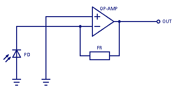
In the amplified detector circuit (transimpedance amplifier) depicted above, the photodiode is reverse biased to produce a linear response to the applied input light. The output level is based upon the incident light (and the wavelength) and can be viewed on an oscilloscope by attaching a load resistance on the output.
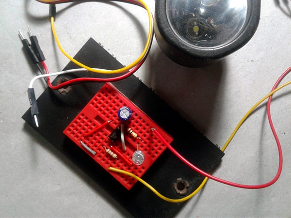
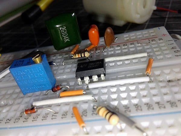
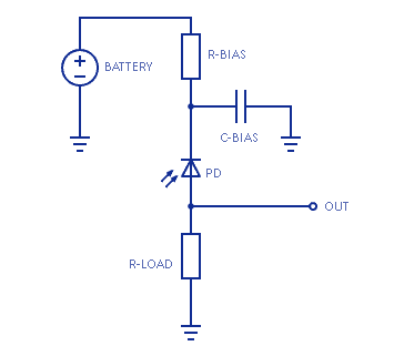
Next in line is a practical circuit for basic photoelectric light sensor experiments. See the circuit diagram shown below.
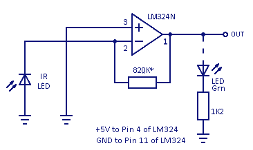
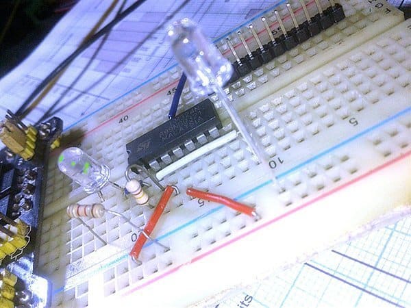
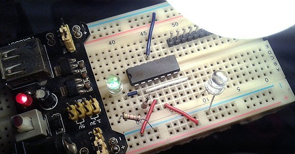
The circuit is built around one-part of the quad comparator IC – LM324N. The circuit was tested with one generic infrared LED (IR LED) as the photodiode. Of course, infrared LEDs emit infrared light when a suitable voltage is applied, but a lesser-known fact is that they also produce a feeble voltage when exposed to light, specifically if it’s in the frequency range that they can handle.
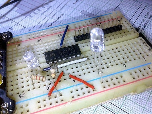
The spectral sensitivity range of the SFH213 (not SFH213FA) is 400-1100nm, whereas the spectral sensitivity of an infrared LED (even when used as photodiode) is rather very limited (for example 750-1100nm only). Anyway, it’s observed that the final output of my test setup (pin 1 of LM324) delivers around 3.6V when the infrared LED is in the very close vicinity (<15mm) of a 40W incandescent lamp. So far so good! See, I used one 820K resistor as the feedback resistor, but you can tweak it in your test setup if necessary.
The significant feature to note from theory is that one can use a photodiode with an amplifier for the purpose of achieving a high gain. The gain of the circuit is dependent on the feedback element. It’s possible to choose whether to run it in photovoltaic or photoconductive mode. In photovoltaic mode there’s zero volt across the photodiode that eliminates the possibility of dark current. In photoconductive mode the photodiode is reversed biased (see below for the basic scheme), thus improving the bandwidth while lowering the junction capacitance.
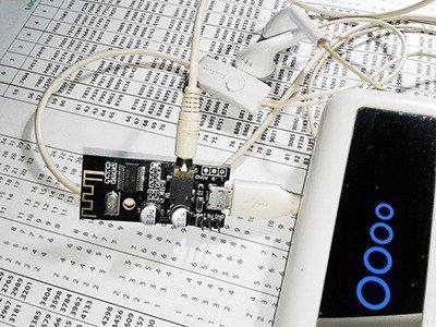
While it is fun to play around with common photodiodes and basic photoelectric light sensors there’s room for more. So naturally, connecting it to a microcontroller is the next step. I’ve already a project for that in the queue and it will eventually show up here.
Further Reading…