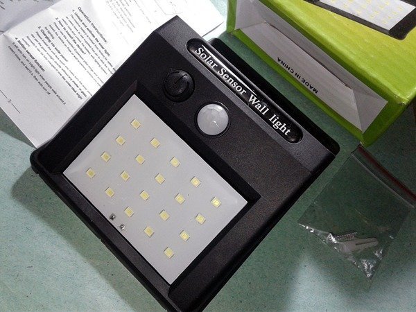
I made a little purchase in the midway of December, and there’s a nice packet waiting for me when I got home from Xmas holidays – A couple of AC230V/2000W light dimmer/speed regulator modules! The module’s electronics is nothing but a simple TRIAC based design, so it’s time for me to brush-up my erstwhile knowledge on mains-operated light dimmers and speed regulators. Back into the Analog Jungle!
A bit of theory and practice
Why a triac? As you may well know, a triac can be used to build very efficient AC lamp dimmers and speed regulators by using the ‘phase-delayed switching’ method. In this technique, the triac is gated on (in each power half-cycle) at some controlled phase-delayed time after the start of each AC half-cycle. Thus it’s possible to control the mean power fed to the lamp/load.
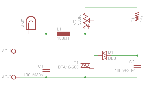
The most common way of getting variable phase-delay triac triggering is to use a Diac with a C-R phase delay network as shown in the basic (AC230V) schematic given below.
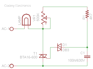
In this ‘textbook’ schematic, components VR1-R1-C1 provide the variable phase-delay. Next schematic is really a simple variant of the first schematic but with the addition of one L-C filter in the feed line, just to suppress RFI.
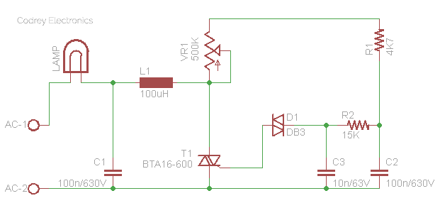
Now you’ve a basic lamp dimmer circuit with RFI suppressor. In practice, this circuit has a minor drawback (often left unnoticed). That means if you dimmed off the lamp by raising the resistance of VR1 to a certain point, it won’t come up again until VR1 is tuned back to just under that value, and then the lamp burns at fairly high brightness. This ‘hysteresis’ can be reduced to a great extent by adding a current-limiting resistor R2 in series with the diac D1 as pointed in the next schematic. See, there’s also a new capacitor C3 to follow the C2 phase-delay voltage to trigger the diac D1.
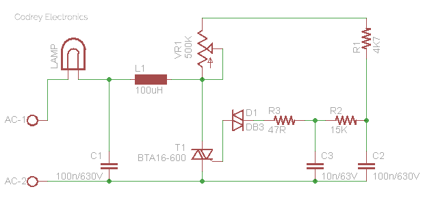
If you’re not extremely satisfied with the above trick, then you can include one more resistor R3 in the same path as shown in the next schematic.
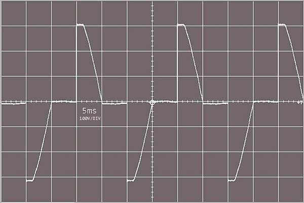
So how does the concept work? Well, as stated previously, the core of the circuit is basically an adjustable delayed pulse generator, and the way it works is that the start of each AC mains cycle gets switched off, and then only after a particular time the triac gets fired. Below you can see in the oscillogram depicts what it looks like (as measured through a differential probe). The entire AC mains cycle is 20ms (50 Hz). Half of the cycle is then 10ms, and in the mid-range setting, each half of the sine wave is switched on after about 5ms (halfway into the sine) at the peak voltage.
Be careful – Never probe your oscilloscope directly into a mains-connected circuit as the scope probe’s ground connection might make a closed loop with the mains terminal and blow up everything in the path, including your oscilloscope, and even yourself!
There’re several ways to get over the costly disaster. The most recommended (but outrageously expensive) method is to use a differential probe as the front-end of an ordinary oscilloscope. Luckily, a cool proffering came on the market, and that particular differential probe (Micsig Differential Probe) can be had for about $170. Comparing all high-voltage differential probes in the market, you’ll find it’s very cost-effective http://www.micsig.com/html/list_69.html

AC230V/2000W Triac module – A sensible choice or not?
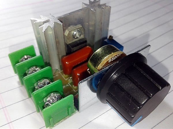
For a sound judgment, it’s necessary to go through a quick electronics breakdown. So, let me start with my retraced schematic (see below).
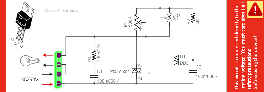
As you can see, the workhorse here is a BTA16-600C silicon bidirectional thyristor (T1) from ON Semiconductor (http://onsemi.com) with an on-state current rating of 16A RMS at 25°C. This solated triac can be clamped directly to the device frame or heatsink. Apart from the big ‘user-control’ potentiometer (P1), there’s also a small multiturn trimpot for fine adjustments (P2). The snubber circuit (R1-C1) is to prevent the triac from spurious turn-on. The snubber consists of a mains-rated capacitor and a mains-rated carbon composition resistor connected in series. Typical component values are 0.1 μF and ≥100 Ω. A carbon composition resistor is required to handle the repetitive surge currents without burning out.
As far as I know, a snubberless triac typically don’t require an external snubber circuit because of its enhanced commutation performance. But there’re certain exceptions as pointed out here http://www.elec.canterbury.ac.nz/intranet/dsl/p90-links/doc-include/power_electronics/snubber_circuits_and_triacs.pdf
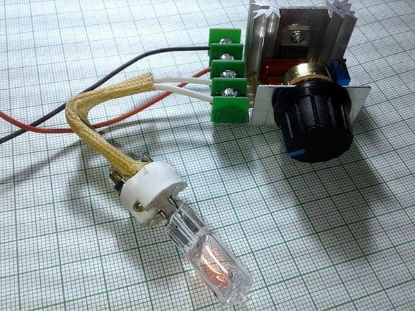
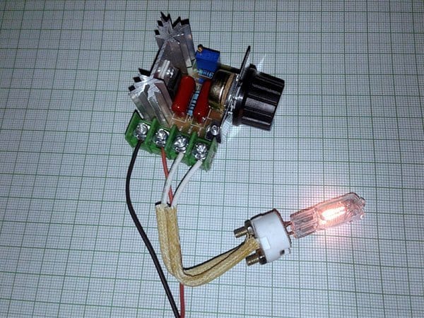
Does it work? Sure, turning the knob will definitely adjust the output accordingly – but not very tightly controlled. For simple uses, this crude approach is fine as you can control AC230V incandescent lamps, Ceiling fans, Hand drills, Jigsaws, etc at ease. Further, just like a light bulb, the module can ‘dim’ a common soldering iron just fine this way. At first, I tested my module with a 230VAC/50W halogen bulb (see the casual snaps), followed by a 230VAC/1000W room heater rod, and my 230V/500W jigsaw. Yes, all things worked, and I lived to tell about it 🙂
Considering the BTA16-600C triac, it’s designed for high-performance full−wave ac control applications where high noise immunity and high commutating di/dt are required, and features uniform gate trigger currents in three quadrants. Below you can see quadrant definitions for a triac.

In principle, a 3Q triac can be triggered in three modes or ‘quadrants’, whereas a 4Q triac can be triggered in all four modes. My next article in this series will explain the advantages of a 3Q triac over the traditional 4Q type. Stay tuned!