This article comes with the construction points of a do it yourself bicycle headlamp (white) and taillight (red or amber). The bicycle headlamp-tail light set presented here provides brilliant illumination for all bicycles, and can be easily mounted on handlebar, mudguard, rider’s backpack, helmet and more.
Bicycle Headlamp
Did you get it? Now we’re starting from the construction project of the bicycle headlamp. First off, find out its complete (two-part) circuit diagram provided below.
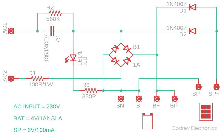
The first session shown above is the mere combination of a rechargeable battery and its battery charger. Even though one 4V/1Ah SLA battery is preferred, you can use any suitable 3-cell Ni-MH battery pack here with zero circuit modification. The AC230V input battery charger is in fact a crude low current capacitive dc power supply, while the solar charger is centered around a small 6V/100mA solar panel. The 3mm red LED in the circuit is the input supply presence indicator which works well for both ac mains and solar panel charging modes.
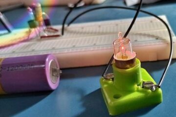
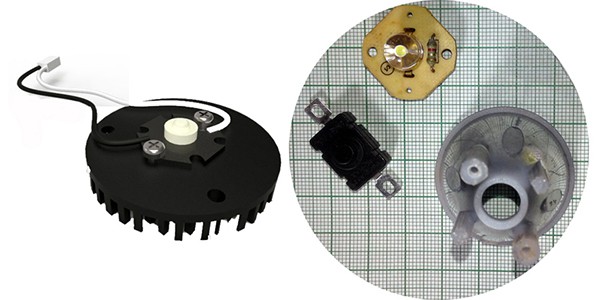
This session covers the headlamp structure. Here, a generic 1W star white LED is used as the bicycle headlamp. In order to get the best from the lamp, it’s needed to employ extra heatsink, lens and reflector assembly with the star white LED. Anyway, you can settle with a cheapo 1W white LED ‘flashlight head’ or else, dealt by your favorite retailer.
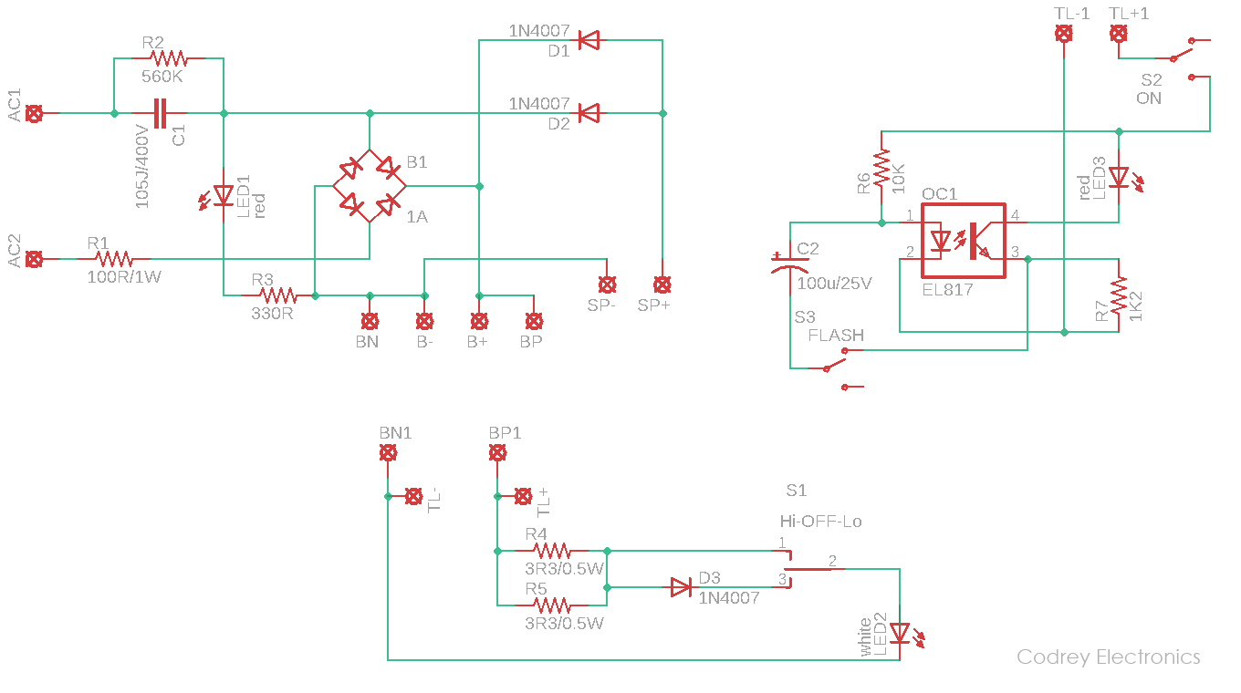
This is the headlamp circuit diagram:
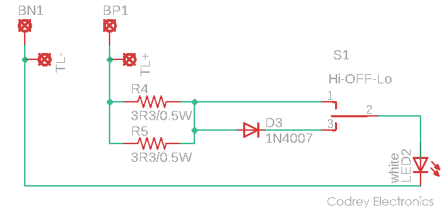
As you can see in the above schematic, an ‘on-off-on’ type control switch lets you flip the headlamp brightness level. A pair of resistors (R4 &R5) wired in parallel limits the lamp current in high brightness (Hi) mode while one diode (D3) also slipped in there in low brightness (Lo) mode. Note that you may need to tweak the resistance value (3.3Ω x2) if demanded by the white LED used in your model.
Bicycle Taillight
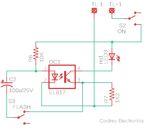
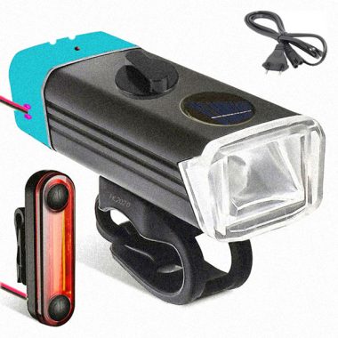
Lets moving towards the next session i.e. the taillight part of the project. The taillight assembly centered on a 5mm (or 10mm) red (or go for amber) also has two modes – steady and flash. Since the estimated output voltage from the battery is in 3.7V to 4.2V range, a good old LED flasher circuit idea is adapted for this scheme. The flashing rate of the taillight LED in this circuitry is around 2.2 Hz, actually determined by the values of RC components. You should use a low-current, high luminance water clear red/amber LED in this circuitry (see below) together with an appropriate plastic reflector and lens assembly. Note that switch S2 is the taillight power switch, and S3 is the steady/flash mode selector switch.
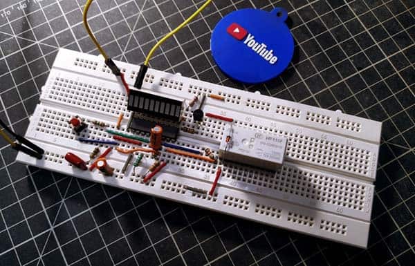
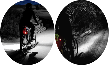
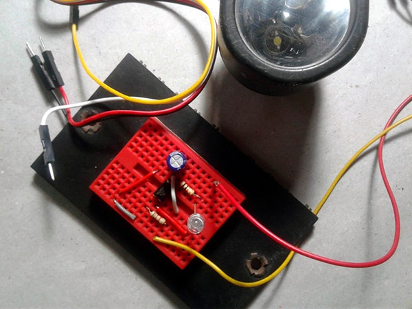
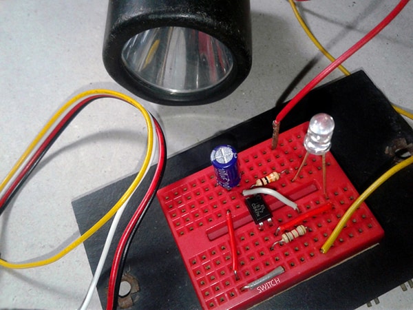
Now, directly to a pair of taillight test snaps from my workbench. You can also watch a quick test movie. Frankly, I fiddled with my video camera settings to try and give a result as similar as possible to the real thing, but failed miserably!
And, the merged schematic:
Construction Clues
As can be witnessed from the proposed artwork shown below, the master device (headlamp) has total control over the system from charging the internal battery to control the main beam. The taillight consists of its own simple electronics and is connected to the master unit using detachable two-core cable. Of course, the construction is more complicated than the idea depicted here. However, with a bit of skill and patience, you can easily learn that art. Lastly, if nothing blowup (no explosion) and you don’t see any smoke, ha ha you have apparently done everything right!
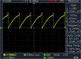
Side note: This is a random scope capture while probed to TP1 of the taillight circuit wrt its Gnd rail.
Quick theory
Time Constant (τ) denoted by the Greek letter tau, τ, represents a measure of time required for certain changes in voltages and currents in RC (and RL) circuits. Generally, when the elapsed time exceeds fivetime constants (5τ) after switching has occurred, the currents and voltages have reached their final value, which is also called steady-state response. And, the rise time (tr) is specified as the time it takes for a signal to rise from 10% to 90% of its final value. For a simple one stage low pass RC circuit, tr = 2.2 τ.
the concluding time
Bicycle light projecting can be trickier than it looks like. I’m pleased to report that whether by skill or by luck I can’t say, but the outcomes are pretty good. Really though, if you attempt this project using the wrong components, it will make things hard to build or impractical to use once the project is complete. Take care to tweak the basic scheme and choose right parts for your project. I’m sure you can think of many more applications where a homebuilt bicycle headlamp-taillight set is much more desirable than a readymade one!
One last word regarding the components – it’s important to ensure that C1 is an X2 type of capacitor suitable for use at mains voltages. It should be marked with a voltage rating ‘250~’ or higher. A DC voltage rating of 630V (and therefore an X2 type) is also adequate. Also, the circuit is often connected to the mains, it is vital to ensure that you adhere to all safety guidelines when building and testing the circuit. That simply means I highly recommend using an isolation transformer (1:1) while performing a ‘hot test’. Even with the isolation transformer fatal high voltages are present, you must be very careful. Protect your creation and yourself!
Well, I’ve gotten you all excited and you want to build one bicycle light, huh? Note that I don’t actually make the final (i.e. enfolded) model, and haven’t tested it with a nighttime cycling. Worry not, I’m sure, decidedly you can!