This post explains how to make a simple touchless live wire detector that can be used to find hidden electrical wiring in a wall or ceiling. This battery powered tester is actually a very simple fun electronics project for STEM kids.
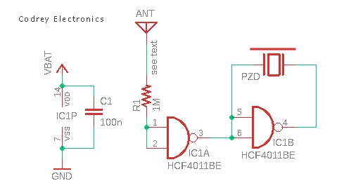
Below is its basic circuit diagram. As you can see, the concept is based on a single IC and only a few extra parts are needed to build it.
The required parts are:
- HCF4011BE IC x1
- 1MΩ ¼ W Resistor x1
- 100nF Capacitor x1
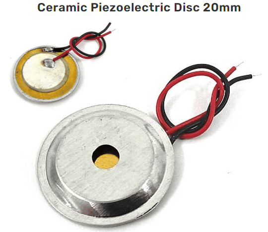
- 20mm Ceramic Piezoelectric Disc x1
- CR2032 3V Coin Cell x1
Note that a ceramic piezoelectric disc (with an aluminium or plastic casing) can be used as a small loudspeaker when powered with audio signal.
Sensitivity of this live wire detector circuit depends on the length of the antenna (ANT). When the antenna is placed near the electrical wiring, then the piezo disc (PZD) produces a sound with 50Hz frequency. A 15cm long piece of rigid 18SWG copper wire can be used as the antenna. The piezo disc is wired in bridge configuration to achieve ample loudness.
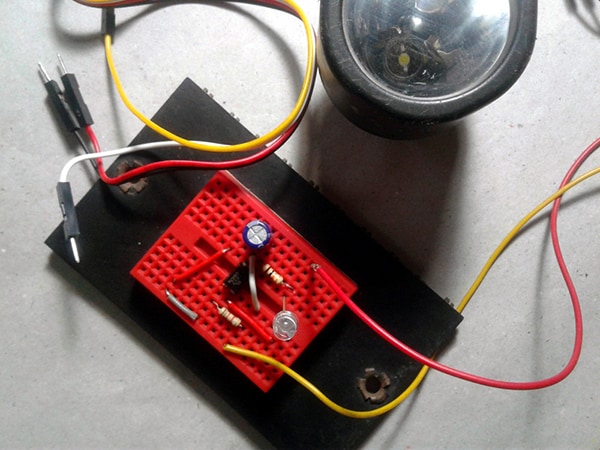
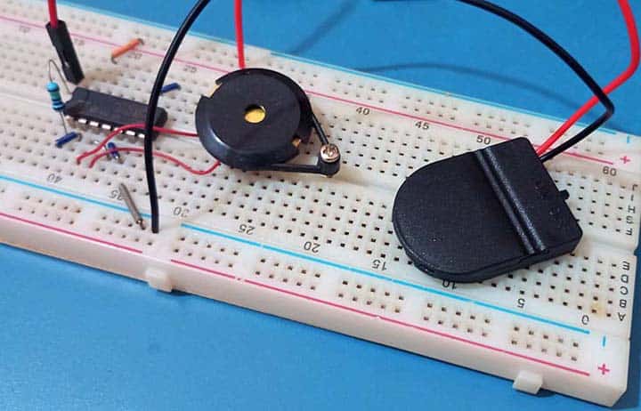
My first prototype was built on a breadboard to do some quick tests. As you can see below, I used another 20mm piezo disc taken from a discarded digital multimeter. Similarly, I used a 3V coin cell packed inside a CR2032 cell holder with an on/off slide switch. The antenna at that time was a 15cm common breadboard jumper wire.
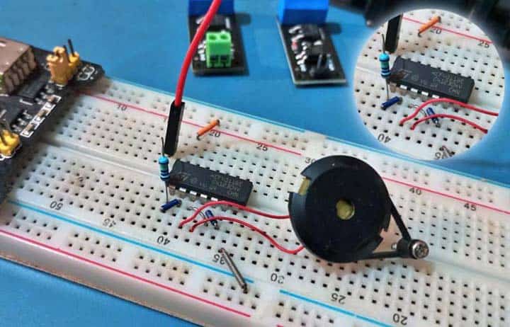
Nothing substantial, but I tested my breadboard mock up with a regulated 5V breadboard power supply as well (see below). Anyway, in my field tests, the best results were obtained when powered by the 3V coin cell.
Working principle of this circuit is fairly simple and straight forward. When the antenna is located near a live wire, the 50Hz interference is amplified by the IC and as a result the piezo disc starts buzzing at 50Hz frequency.
The HCF4011BE is a Quad 2 Input NAND Gate IC available in 14-pin DIP package. All of its inputs and outputs are buffered. It operates over a recommended VDD power supply range of 3V to 20V referenced to VSS (usually ground). Unused inputs must be connected to VDD, VSS, or another input.
The entire circuit, assembled on a small piece of perfboard, can be enclosed in a suitable plastic pencil box. Correctly assembled circuit does not need any special adjustment, but the antenna must be kept as far as possible from the hands of the user.
You have probably seen cheapo tester pens that detect live wires in home wiring without having to actually probe the wire. The contactless probe in such a tester pen picks up the changing magnetic field around the unshielded AC wire. Still, construction of a similar tester circuit is very educational, especially when the maker takes time to figure out how it works. Also it would be interesting to play with variations of the crude circuit idea presented here.
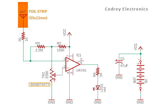
Next is another circuit idea for you to try, a slightly different live wire detector with a visual indicator. And it uses a thin copper foil strip as the antenna!
This inspired design is centered on the commonly available uA741 op-amp IC.
Well there is not so much to say about this. See you next week, everybody. Have Fun!
Explore a wide range of Embedded IC Chips at Ampheo Electronics, offering accurate and comprehensive options. Request quotes effortlessly!