I’ve a few mini pocket weight scales. What I love about the cheap device is that it uses a pretty little load cell. When a scale get worn out, perhaps you can reuse its 4-wire load cell in another do it yourself project. Well, it looks like it’s time to hack one of the defunct mini pocket weight scales to get some ideas to play with.
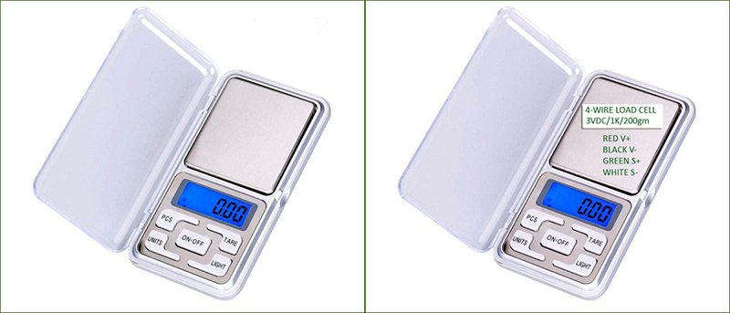
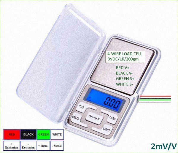
A quick inspection of the load cell makes it more understandable. As pointed above, the load cell in front of me is a 4-wire, resistive type, designed for 3VDC (5VDC tolerable) operation. It’s small enough, but has a capacity of 200 gram, and a gauge resistance of 1KΩ. The typical signal output span per volt of excitation is 2mV, hence 10mV at full load when excited by 5V. Note that usually the output from a load cell will be approximately 0mVat zero load though typically there may be a small offset voltage at zero load. Over the full rated capacity of the load cell the mV output will change, and the amount by which it changes depends on the resistance change in the load cell and on the excitation voltage applied.
Since there is no standard wire color code system for load cells, you will need to know from data supplied with the load cell which wires are the excitation (E+ and E-) wires and which wires are the signal wires (S+ and S-). If you do not have the information, then take your multimeter to measure the resistance across each pair of wires in turn and record the results. Remember, the resistance across excitation wires is usually the highest resistance measured across any two wires. If the resistance tests and mV output tests of the load cell appear to be correct, then preserve the load cell and the test record as it might help you later when you integrate the load cell into a special project.
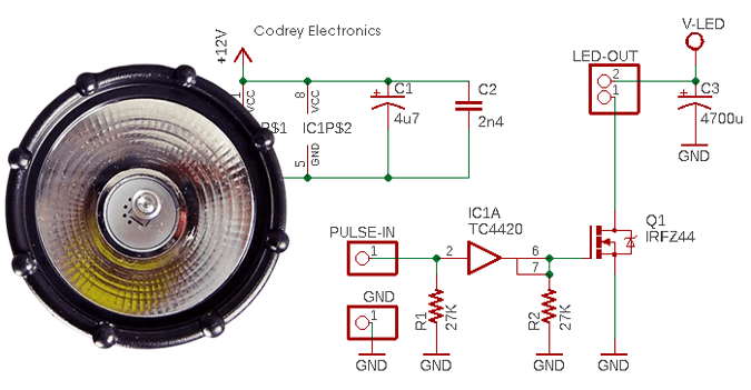
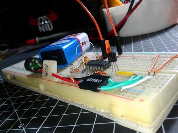
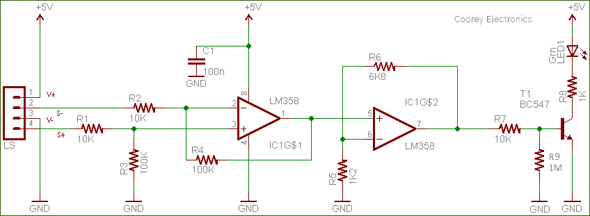
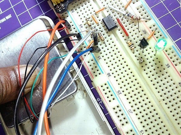
Actually my goal was to check the suitability of the load cell for a funny ‘pressure sensor pad’ project. So for my specific experiment, I just built an ‘amplifier’ to convert the tiny resistance changes of the load cell into a readable voltage output. See the schematic of that setup I used for my initial tryout which’s based on one-part of an LM358 chip.
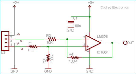
Nevertheless, a mere replication of the classic differential amplifier circuit. The setup might be adequate for some differential applications as it can amplify a bridged signal and can have good CMRR. But this classic differential amplifier idea has a few problems.
Anyway, with zero weight applied, the output voltage was about 70mV (5V excitation), and when squeezed the load cell very hard, there’s a noticeable uplift in the output voltage level (~180mV). And then, I added a second stage with an approximate gain of 6 (see below schematic) and got around 450mV and 1200mV output voltage levels respectively (I still trust my bench top digital voltmeter).
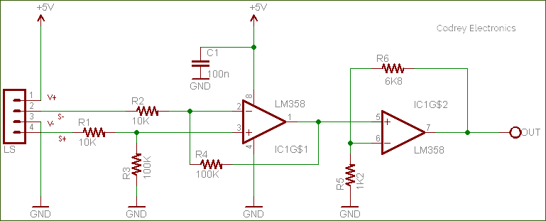
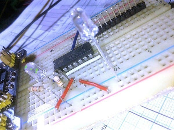
Thereafter, I added one LED at the output of the circuitry for visual inspection. See the updated/final schematic.
The described idea, though a crude one, will be adequate for a simple pressure sensor pad that can capture physical force contact to generate some sort of a response (identifying force thresholds to trigger a pertinent reaction). Certainly, this concept gets more complex depending on the critical demands of the real application, especially when it comes to precise detection (and measurement) of relative change in force or applied load.
Don’t follow the trail!
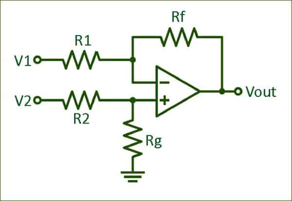
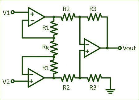
Let’s leave the crude idea now as it’s ineffective in many situations. Better, take a look at the classical instrumentation amplifier. Since instrumentation amplifiers excel at extracting very weak signals from noisy environments, they are widely used in circuits that employ sensors that take measurements of physical parameters (like our load cell). A load cell will often be implemented in a Wheatstone bridge that renders a floating differential signal. Luckily, the instrumentation amplifier can amplify floating signals because it only amplifies the difference between the two input signals.
List of instrumentation Amplifier (IA) ICs quite popular in hobbyist’s/maker’s world includes the INA122 and AD8422 – both are excellent single-supply Rail-to-Rail instrumentation amplifiers. Since I wanted to continue the load cell hacks but I didn’t have a bare dedicated instrumentation amplifier test board, I made a move to the following simple scheme based on INA722P. And everything worked well and as expected.
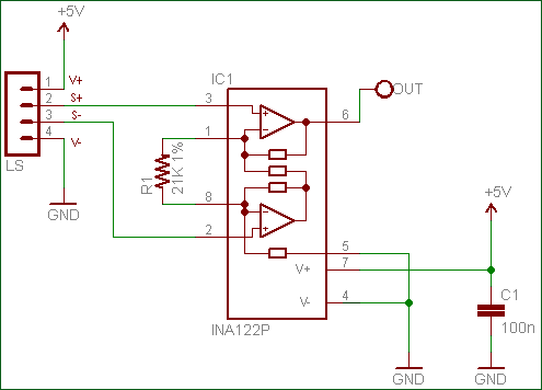
Here, the gain is set by R1. If output level shift is desired, then you should add a voltage divider to offset the output signal. For more, read from page 7 of the INA722 datasheet published by BURR-BROWN™.
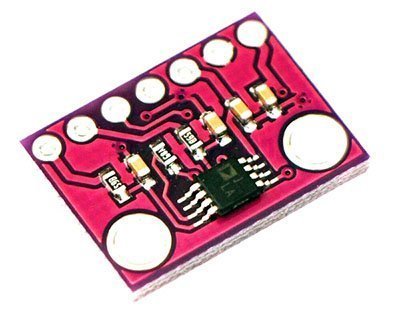
Even though almost all instrumentation amplifier ICs are pricey components, I bought these small AD8221AR breakout/carrier boards too to play with. I am happy with these cheapo modules, even when they had pretty much no information, online. I intend to extend this session – please look back soon.
Further, it’s shown in this primer (https://www.codrey.com/arduino-projects/how-to-build-a-digital-weight-scale/) how to utilize a standard load cell, a HX711 breakout board, and an Arduino Uno in order to measure weight. The HX711 is a 24-bit analog-to-digital converter (ADC) which fits perfectly to digital weight scale projects. So, in order to easily build your own weight scale, simply follow the primer, and try to develop the basic idea. There are many cool projects you can then do.
Stopping point
Of course, there is often more than one right answer to any design challenge and there are numerous ways to cook up a sensor interface. I hope, now you know how to start playing with small load cells lifted from defunct digital weight scales (purchased load cells, as well). But it won’t make much sense until you do some experiments. So start up the soldering iron!
You may also be interested in learning about the construction of anew pressure sensor pad and/or a full-fledged digital weight scale. Pretty soon I will hopefully also do experiments with them.
Have a question? Leave a comment and I’ll respond!