Picking out a laser diode and its driver for your next design can easily turn into a multi-week project. Not only is it difficult to find the right laser diode in the highly fragmented market, it’s often even more difficult to get timely information which will help you which driver best fits your needs. This article, which is in fact a bit belated sequel of my previous primer, will hopefully provide you with a basic understanding of the most crucial factors to consider when making your choice. So, let’s get started!
The baffling problem
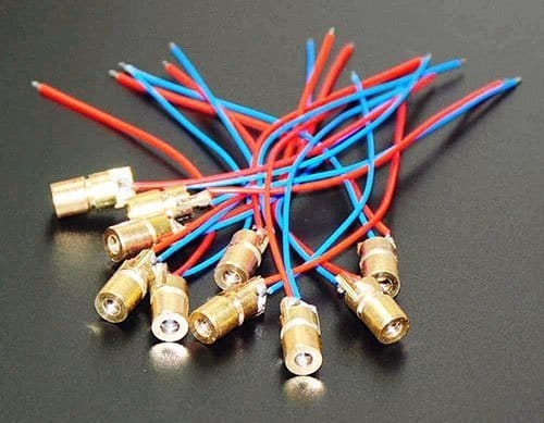
To understand the basics of a commonly available and cheap 5mW laser diode, refer to the above photograph. This type of laser diode is usually described by its sellers as “650nm 6mm 5VDC 5mW Red Laser Dot Diode Module”. In its most basic form, laser head of the module is composed of a small laser diode, condenser lens, and adjustable copper sleeve. As claimed, the module can work directly with a 5VDC/40mA power supply, but that’s not the case always. Before the first run, you should pay attention to the laser module because some modules are available with an onboard current limiting resistor, and some modules are just ‘plain’ modules i.e. they don’t hold the onboard fixed resistor. Beware, laser diode (modules) are extremely sensitive and will be damaged immediately by static electricity and/or over voltage/current. So, do not connect the laser diode (module) to a power supply before you are sure that it’s ready to work with that voltage (and current) level.
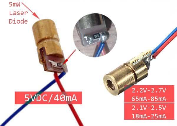
The above figure points the finger to another problem. We can often find a 33Ω (or so) current limiting resistor in 5V labeled laser diode modules. Anyway, the typical ratings of discrete laser diodes varies from model to model – If the operating voltage (VOP) of one laser diode is in 2.2V to 2.7V, the other one has a 2.1V to 2.5V range. The same slip applies to the operating current (IOP) range as well. Difficult to handle – indeed!
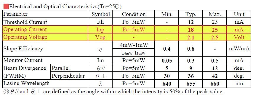
This is a snippet from the official datasheet of a 650nm laser diode. Thanks to Union Optronics Corp. Taiwan (R.O.C.).
Role of a laser diode driver
If you want to play with a laser diode then you must have a laser diode driver circuit as it helps in limiting the operating current of the laser diode. The simplest and least expensive method is the use of a fixed resistor as discussed earlier. Just a slight indication – I got 33Ω resistor in most 5VDC modules, 22Ω resistor in 3VDC modules, and 180Ω resistors in 9VDC modules. May be an arbitrary choice – who knows?
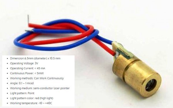
Needless to stay, if you don’t have the datasheet of your laser diode (module), then start cautiously with resistors of higher values. Isn’t easy to use a laser diode (module) when you have no datasheet or some instructions, the chances are that you’ll probably burn it within seconds if you apply a current/voltage greater than the maximum operating current/voltage. The cheapo module I have was bought on Amazon and it has 2 wires – red (+) and blue(-). I began the game with a 270Ω resistor and later I found that a 100Ω resistor was giving reasonable brightness without burning it. Thereafter, I got a bunch of new 3V/5mW red laser modules from a Chinese seller, fortunately the batch came with a credible technical description (see below). I tested one of them at 5VDC with a 47Ω resistor.
My quick advice is to start the trial with a 100Ω resistor for 5VDC operation when you have an unknown 5mW red laser module that does not have an onboard fixed resistor!
Let’s look at it further
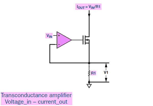
To be honest, the aforesaid fixed resistor method is a layman’s trick. Sometimes, it’s nice to just make something because it works nice. But the elegant solution is to use a constant-current (cc) source for safe driving of laser diodes. This is a basic constant current source based on an op-amp driving a power MOSFET. When a transconductance amplifier (voltage-in/current-out) is required, it can be made with a single-supply op-amp, a MOSFET, and a precision sense resistor (R1) that defines the transconductance, as shown in the below figure. Here, the voltage on the MOSFET’s gate sets the current in the MOSFET and R1 such that V1 (the voltage across the sense resistor), equals the input voltage (VIN). Reference – www.analog.com/analogdialogue.
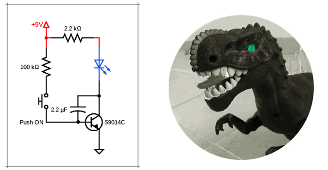
Let’s now consider a real-world circuit example. The constant current driver circuit created (see below) is very simple and does not need many explanations.
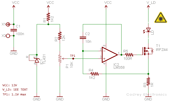
The circuit itself is quite simple: the op-amp (IC1) regulates its output voltage such that the voltages at the inverting (-) and non-inverting (+) inputs are (virtually) equal. Hence, the voltage drop across the sense/shunt resistor (R3) will be equal to the reference voltage (TP1), set by the multiturn trimpot (P1). The inclusion of the RC components (R4-C2) forms a low pass filter (to ensure stability). In short, the IC1 and T1 ensure that the voltage over R3 is kept equal to that coming from the reference, resulting in a constant current through the laser diode (LD). A tad compact, as you can see. I’m happy with the result!
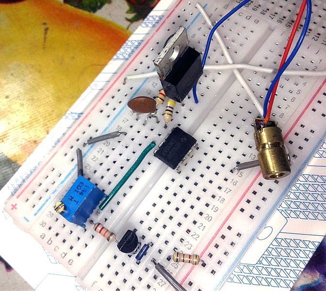
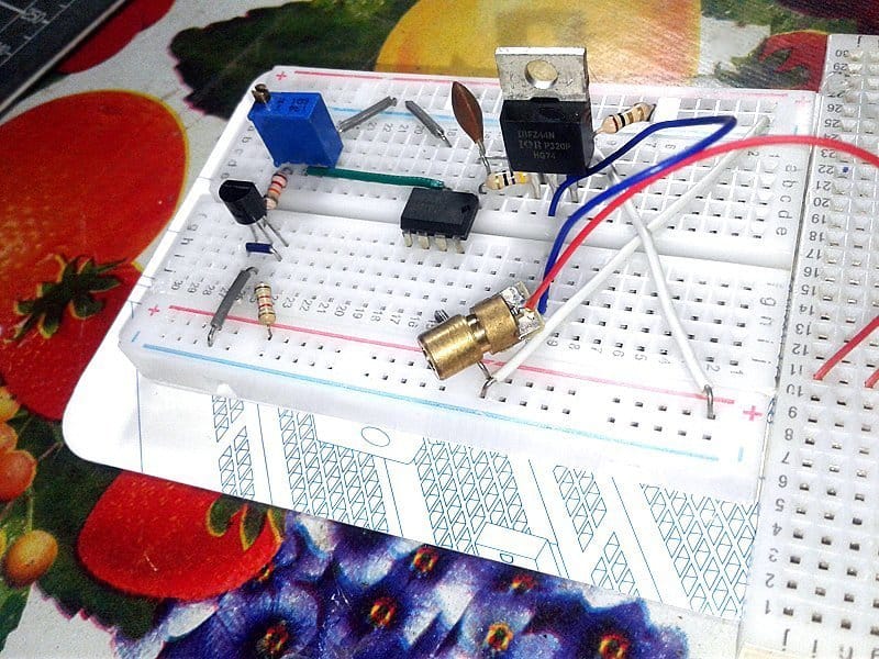
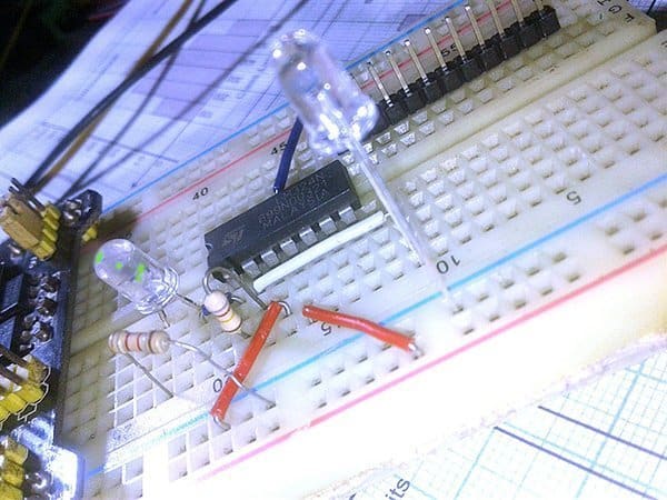
The quick breadboard test setup (still incomplete) can be seen below.
Note that the trimpot P1 in the circuit allows you to set the reference voltage anywhere between 0 and 1.1 volts. Similarly, the shunt resistor R3 determines the maximum current the circuit will provide when you turn the trimpot up to maximum. Calculation for its value: R3 = 1.1V/Imax. One very important aspect is the choice of the laser diode power supply (V_LD) – it must cope with the typical VOP of the laser diode. For example, typical operating voltage of a standard 150mW red laser diode is 2.6V (3V maximum), and the typical operating current is 280mA (350mA maximum).
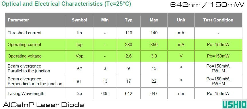
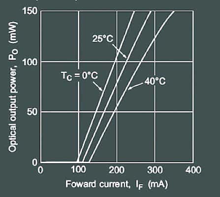
Also, note that the most common of the diode laser characteristics is the L/I curve (look up next figure). It plots the drive current applied to the laser against the output light intensity. This curve is used to determine the laser’s operating point (drive current at the rated optical power) and threshold current (current at which lasing begins).
TTL and Laser Control
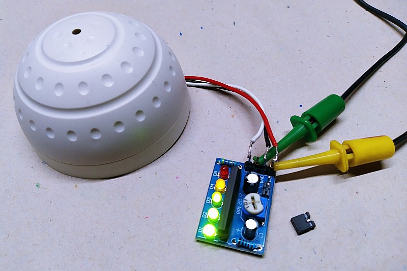
Quite often I get queries about TTL and Laser, and recently I began thinking deeply about that. Thereafter I immediately had a look in some online listings and found enough stuff to prepare TTL modulated diode lasers for my next level experiments. This is the photograph of such a laser driver board with TTL control, I came across online. Now I’m able to modulate a laser beam by a TTL (Transistor-Transistor-Logic) input signal.
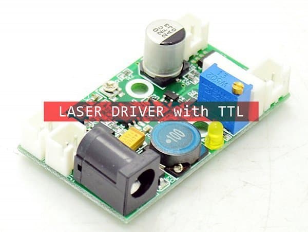
Now to its key specs:
- Input voltage: 8-14VDC
- Circuit Control: 12VDC step-down circuit, constant current output (current and voltage are adjustable)
- Output Specifications: Max 2.1A
- Scope: 200mW-3W 405nm/445nm/450nm/520nm red, green and blue laser drive power
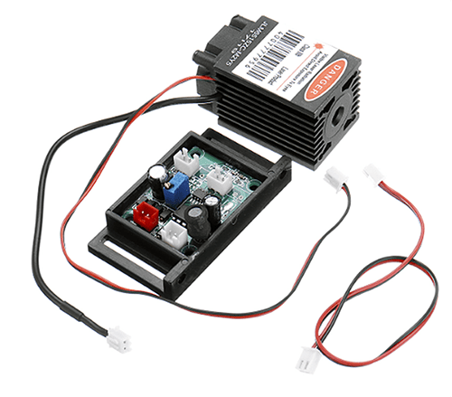
And, see a 150mW ready-to-use Laser Kit sold by Banggood:
More on this later. Right now I plan to build a simple laser diode driver with TTL control input. That do it yourself project will be published here after some weeks. Stay tuned to learn how to control your laser beam with a TTL (and PWM) signal.
Today’s laser diodes are comparatively small and more efficient. They can be directly modulated but can be frustrating to work with. And that is it, I hope you enjoyed this post and learned something new like I have learned to play with diode lasers!
I read your article with much interest. However my electronic skills are not on par with yours.
But I’m waiting for the TTL article: ” will be published here after some weeks. Stay tuned to learn how to control your laser beam with a TTL (and PWM) signal. ”
Also, hope you have an idea about the following:
I have a ML101J25 laser (80mw optical output) and it should accept up to 150mA.
https://www.mitsubishielectric-mesh.com/products/pdf/ml1xx25.pdf
I use a cheap laser driver board
https://www.aliexpress.com/item/33013481466.html
The bench power unit tells me that no more then 100mA is drawn from it, even with the trimpot at max. I feed 3V into it which is the max for that laser. Any ideas? Is the laser driver a mismatch with this laser diode?
I have _completely_ misunderstood the fact that laser diodes are not voltage driven. I knew that a constant current was the most important fact, but I didn’t take into account that the voltage was derived from Ohms law. It’s not the laser driver board that decides what voltage is outputted, it only controls current. You just need to feed sufficient voltage into the laser driver board to output a certain current out of it. (surely you know this, but mentioning this for any other readers…)
After this insight, I fed 5V into the laser driver board (the max for this board) and now the current can go up to 150mA, which is the max for this laser. Now I have additional brightness too! It seems that the laser is now working at it’s optimal conditions.
I would suggest, for any laser beginners (like me), to watch the first 6 minutes of this video:
https://www.youtube.com/watch?v=AnSVQYDvJE0
Chris:
Thanks for your valuable comments. The promised article will be published soon.
I’m glad to note that your LD is now working! As you’re aware well, a laser diode driver is a constant current source,
Laser diodes, in principle, are current driven (and current sensitive) semiconductors, and a change in the drive current equals a change in the laser wavelength and output power. So, you should always use a dedicated constant current power supply for your laser diode(s). This is just for your leisure reading https://www.laserdiodecontrol.com/laser-diode-driver-basics-and-fundamentals
& Thanks for the YouTube link too. It’s awesome to watch the really useful explanation. Have fun and don’t be hesitant to get back to here 👍
Hello mate,
I was planning to put together 5 of these laser diodes. I bought the 5V one. Is it safe to say that i can connect them in parallel on the driver circuit that you build?
I hope to know your output on this.
Thanks
criel
@criel: The given circuit configuration allows a maximum drive current of around 1A. Therefore, calculate the total current consumption of your proposed laser diode setup yourself so that you can change the basic driver circuit later as needed. Thanks!
If the current is 30mA the dissipating power should be around 60mW, I wonder if the 5mW is the light power
@Marco A. No doubt, a 5 mW laser has an ‘output’ power of 5mW. Also note that a CW laser is always defined in average output power. Thanks!