The electronic flood alarm circuit presented here is wired around an LMC555N (IC1) – CMOS version of the bipolar 555 timer chip. IC1 is followed by a complimentary pair of emitter followers (T1 and T2) to drive a standard 8 ohm loud speaker (LS1). Only one 9 volt alkaline battery is required to power up the whole system.
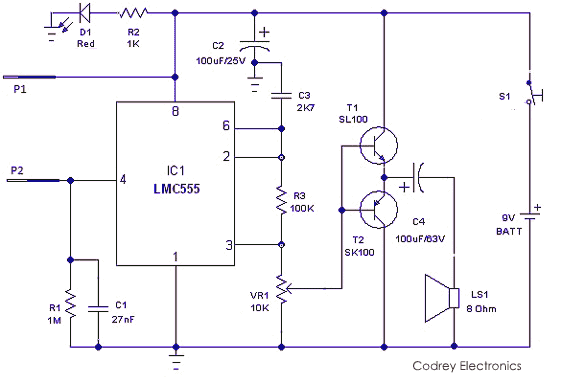
The circuit has the power applied whenever the power switch (S1) is activated. The reset input (pin 4) of IC1 is held low by resistor R1(1M). When the sensor probes (P1&P2) become wet, they conduct to reverse the state of IC1’s reset terminal ,and as a result the astable multivibrator starts oscillating at a frequency determined by the RC components R3 and C3 (normal water is always slightly contaminated, and thus conducts electricity to a certain extent). The output of IC1 (square wave @ 2.6KHz) drives the complimentary pair made of T1 and T2. A volume control (VR1) is also included between the output of the IC1 (pin 3) and the bases of T1 and T2.
The probes can be two suitable galvanized needles, or two small pieces of circuit board with the copper surface coated with solder. The probes are fitted at the lowest point where water will come to stand. After construction, the alarm circuit must be fitted somewhere that will remain high and dry. Use a pair of thin twisted flexible wires to connect the probes to the circuit, and tweak the value of R1 (1M) to increase/decrease the detection sensitivity.