The common mains power resumption alarm will activate an internal buzzer in the event of a mains power resumption after a power cut or power interruption. Such a portable alarm can be used in and around your home as it’s a little device useful for when you need to be informed whilst you are working outside, or in a different building.
Normal mains power resumption alarm simply always switches a sounder on and off. But the design presented here is a bit dissimilar because it comprises a small automatic emergency lamp and an audio annunciator.

This device gives a brief audio indication of the resumption of mains power. When mains power is absent its in-built white LED awakes to lights up its surroundings. The device also has a provision for recharging its battery pack when mains power is available.
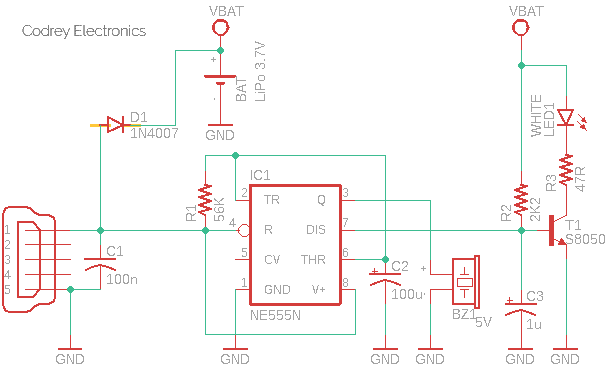
This is the circuit diagram of the mains power resumption alarm and emergency light.
The circuit needs an external USB power supply (the common smartphone travel charger) not only to ‘signal’ the mains power state but also to recharge the internal battery pack. Then you can operate the emergency light with that backup battery during a blackout.
As you can see in the above circuit diagram, the circuit uses a NE555N (IC1) at the input to perceive the mains power status. This time IC1 is configured as an inverting buffer i.e. the output logic state (low/high) is the inverse of the input state. During initial powerup or power resumption, the input of IC1 (Pins 2+6) sees a ‘low’ level, thus its output (Pin3) goes ‘high’ to drive the active piezo buzzer (BZ1) for a finite period. Note that a low (< 1/3 Vcc) input makes the output high. However, the 100uF capacitor (C2) gets charged through the 56K resistor (R1) within a few seconds (~ 6 seconds). And as a result, the output goes low since the input voltage level then raises above 2/3 Vcc (>2/3Vcc input makes the output low). This makes the piezo buzzer silent. Note that when a voltage is applied to a capacitor through a resistor, the voltage across the capacitor rises slowly. This simple online calculator will tell you how many milliseconds are required to reach a specific output voltage, based on the supply voltage (V), the resistor value (R), and the capacitor value (C): http://www.ladyada.net/library/rccalc.html
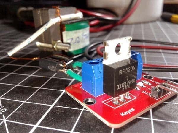
In addition, one NPN transistor S8050C (T1) is used to make the automatic emergency light. The working of the circuitry is extremely simple and straight forward. The driver transistor is biased by a 2.2K resistor (R2) to control a white lamp (LED1) powered by the backup battery – simply a 3.7V/600mAh LiPo battery pack. When mains power supply is available, the discharge terminal (Pin 7) of IC1 disables T1 to switch off LED1, and in case of a blackout, T1 comes into the picture and turns on LED1 automatically.
How it works? Pin 7 of 555 IC has the same logic state as its pin 3 i.e. the signal at pin 7 is in phase with the output at pin 3. The main difference is that pin 3 of the standard 555 IC has a healthy output buffer that can source and sink 200mA of current while pin 7 can only sink moderate current (<50mA) to the ground. Remember, Pin 7 is an open collector output gives you a solid ground or no output at all, so its collector voltage source is not committed to Vcc. You could connect it to the same (or different) voltage source and use as an output if desired. See internal diagram of 555 IC https://commons.wikimedia.org/wiki/File:NE555_Internal_Circuit.svg
While getting back into the lamp and driver, LED1 is wired to the collector of T1. Just looking at T1 with R3 and the LED1, we can see a so-called low-side switch. T1 is a 700mA (Ic) NPN bipolar junction transistor (BJT) – means it conditionally allows 700mA of current to flow from its collector to the emitter proportional to the current which is flowing from the base to the emitter (here the current can only flow from the collector to the emitter and from the base to the emitter, not in any other direction). In this rather simple application, T1 works as a simple current-controlled switch i.e. by directing a current down the base, we allow a current to flow into the collector.
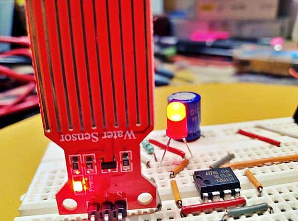
A single LED snipped off from a cheap 4V SMD white LED aluminum strip was used in my breadboard prototype. You could also use a 5mm warm white LED (or the like) here without a major design alteration. There is an open question as to why I chose to put a 4V rated SMD white LED in a 3.7V (nominal) battery-powered circuit. The answer is that I wanted to run a low-profile white LED on a lower-voltage supply with lower (but plenty) brightness just to lengthen the backup time. If a device works, the plan has not gone wrong!

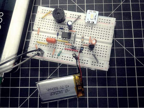
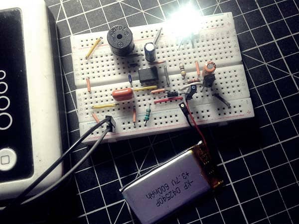
Now let me show you a couple of snaps of my breadboard setup.
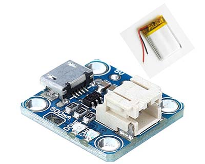
If looking at the LiPo battery charger section of the design, the only component you can find is a 1N4007 diode (D1). The 1N4007 diode is wired in series with the 5V USB input and the 3.7V/600mAh ‘protected’ LiPo battery (BAT). Admittedly, this is the dirtiest part of the circuit. You can certainly refine this portion by employing a safe charging circuit with the help of a dedicated Li-ion/LiPo battery charging IC like the common TP4056 or MCP73831 or LT4054. Now, I’ll refer you to the linked articles and projects posted here before, since I can’t really go into the electronic depths of LiPo batteries and battery charging circuits again. If you are a bit lazy like me, opt for a prewired charger module (see below).
And, that’s all for now. Use the comments box if you need any help. Have fun!
