Are you ready to go back into the old school electronics again? If so, be prepared to forget about microcontrollers for a few moments! This time I’d like to share my random thoughts on certain oscillator circuits. Okay, let’s start making some funny waves…
Every signal starts with an oscillation! The pendulum is a good example of a non-electronic oscillator – the physics behind a pendulum is known as “simple harmonic motion”. See, the theme of this post is electronic oscillators, so let’s make a quick jump to that playground.
Electronic Oscillator
Electronic oscillators are great circuits used to make waveforms using much of the same basic physics of the pendulum swing. The purpose of an electronic oscillator is to generate a required waveform. An electronic oscillator circuit basically has two segments or functions – generate a frequency and amplify it. Since the two segments create a loop, the oscillator circuit has got a feedback mechanism.
Phase Shift Oscillator
Actually, there’re a number of oscillator types that are often used in both hobby and professional electronics, but this time I’d like to cover just one – the phase shift oscillator which usually employs resistors and capacitors to provide oscillations.

The output signal of an amplifier is either in-phase (non-inverted) with the input signal, or 180° out of phase (inverted) with the input signal. The phase shift oscillator uses this fact with a suitable feedback circuitry to set the feedback signal in phase with the input, thus adding to the input signal.
BJT Practical Circuit
Below you can see the basic circuit idea of an RC Phase Shift Oscillator. The single bipolar junction transistor (BJT) based circuit uses three RC pairs. The three RC pairs cause a total phase shift of 180° (60° x3) so it’s used with the BJT inverting amplifier. Note that the inverting amplifier contributes 180° of phase shift, and the remaining 180° is contributed by the RC feedback network.
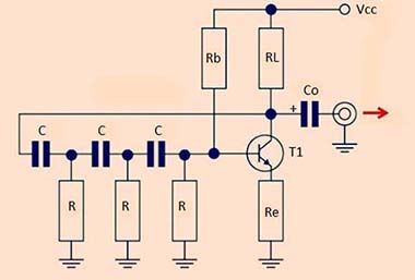
Here, if all of the feedback resistors are identical, and all of the capacitors are identical as well, then the frequency of the filter network f = 1/(2πRC√(2×3)). And, the gain to replace the network loss should be 29, so Re = RL/29. Remember, you need to play around with the value of Re to make sure that the BJT stayed in the linear region. Better, make it variable to allow for adjustment in gain to account for component tolerances and other inherent circuit limitations.
I already conducted a quick test of the practical circuit on a mini breadboard (See the list of components below), and noticed a bit higher value frequency than calculated (650Hz). Not very astounded because it’s on a cheap breadboard (Powered by a 6F22 9V battery). Perhaps, it worked right for me by luck!
- R = 10KΩ ¼ W MFR (http://www.resistorguide.com/metal-film-resistor/)
- C = 10nF Tantalum (https://passive-components.eu/the-basics-benefits-of-tantalum-ceramic-capacitors/)
- Rb = 100KΩ ¼ W MFR
- RL = 4.7KΩ ¼ W MFR
- Re = 180Ω ¼ W MFR (see notes)
- Co = 10uF/25V Electrolytic
- T1 = BC548C (https://www.onsemi.com/pub/Collateral/BC546-D.PDF)
Side Note: A bypass capacitor is used in parallel with Re can improve the AC gain. Further reading https://www.electronics-tutorials.ws/amplifier/amp_2.html . Also, read about the Barkhausen stability criterion https://en.wikipedia.org/wiki/Barkhausen_stability_criterion
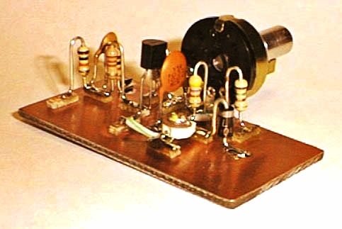
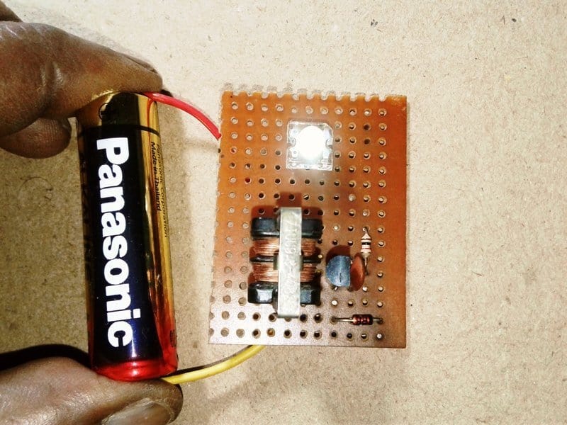
Moreover, it’s worthy to notice that breadboards are not very good for phase shift oscillator experiments. It’d always be better to follow the “Manhattan-style” construction using a small piece of copper-clad board. Next figure shows a typical construction example (obtained from web).
Op-Amp Practical Circuit
Also note that, an improvement on the standard BJT version of the phase shift oscillator can be attained by using an op-amp buffer to reduce the loading on the phase shift filter network. The following practical circuit consists of a negative-gain operational amplifier and a three-part RC network in phase-lead configuration, that produces the 180° phase shift, connected from the output back to its inverting input.
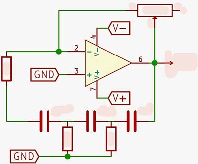
Try this circuit out for yourself with the good old LM741 Op-Amp IC. First off, employ 2.2nF capacitors and 4.7KΩ resistors in the RC feedback circuit to get a reasonably pure sinusoidal output close to 6kHz. The op-amp gain must be equal to 29 in order to sustain oscillations. Since 4.7KΩ value resistor is used in the RC feedback network, the value of the feedback resistor, wired between Pin 6 and Pin 2 of LM741 IC, must be 136KΩ. An appropriate variable resistor as the feedback resistor will help you to find the optimum resistance value that gives the best wave shape and reliable amplitude. The circuit will operate from a 9VDC power supply. In several tested practical examples of this circuit, the actual frequency produced was within a reasonable percentage of the estimated value.
In a nutshell, an electronic oscillator is an amplifier with a feedback network that provides a fraction of the output to the input via a filter or phase shift network, such that the loop gain is unity. Learning how to design and build phase shift oscillator circuits is a useful skill but it does take a little practice. Google will help you find excellent guides on this complex topic, so go for that titbits. A really effective way to learn about electronic oscillators —and while it can be bewildering for first-timers, it shouldn’t take you too long to learn the ropes!
Off topic: Bonus for Arduino Fans! Loved the oscillogram provided below? Actually, this is the quick recap of a little Arduino project done by me before a couple of years.
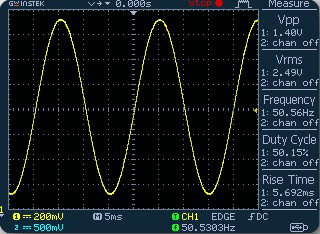
In order to get it, you need to upload the code given at the end of this post into your Arduino Uno. Thereafter, simply add a first-order low pass filter (LPF) at the output (D3/D11) of the Arduino as pointed below. The setup then reconstructs low-frequency sine wave from the high-frequency digital PWM waveform.
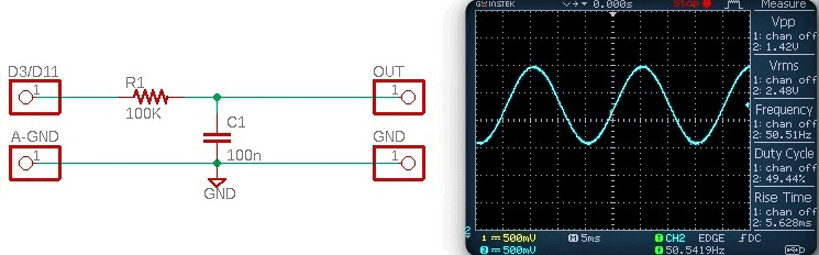
Here, the Arduino is configured to generate the sine wave signal using “Fast PWM” method, and the setup can deliver complementary PWM thru D3 and D11 pins of Arduino Uno.
That’s all for now. Have Fun!
/*
  *Arduino 50Hz 8-bit Sinusoid PWM (SPWM) driver
  *Adaptation of an Open-Source Work
  *Thanks to Ken Boak & Trysatn Lea
  *Authored by T.K. Hareendran/Rev 08.2020
*/

int PWMval = 128;

int Sin_table[255] = {
  128,
  131,
  134,
  137,
  140,
  143,
  146,
  149,
  153,
  156,
  159,
  162,
  165,
  168,
  171,
  174,
  177,
  180,
  182,
  185,
  188,
  191,
  194,
  196,
  199,
  201,
  204,
  207,
  209,
  211,
  214,
  216,
  218,
  220,
  223,
  225,
  227,
  229,
  231,
  232,
  234,
  236,
  238,
  239,
  241,
  242,
  243,
  245,
  246,
  247,
  248,
  249,
  250,
  251,
  252,
  253,
  253,
  254,
  254,
  255,
  255,
  255,
  255,
  255,
  255,
  255,
  255,
  255,
  255,
  254,
  254,
  253,
  253,
  252,
  251,
  251,
  250,
  249,
  248,
  247,
  245,
  244,
  243,
  241,
  240,
  238,
  237,
  235,
  233,
  232,
  230,
  228,
  226,
  224,
  222,
  219,
  217,
  215,
  213,
  210,
  208,
  205,
  203,
  200,
  198,
  195,
  192,
  189,
  187,
  184,
  181,
  178,
  175,
  172,
  169,
  166,
  163,
  160,
  157,
  154,
  151,
  148,
  145,
  142,
  139,
  135,
  132,
  129,
  126,
  123,
  120,
  116,
  113,
  110,
  107,
  104,
  101,
  98,
  95,
  92,
  89,
  86,
  83,
  80,
  77,
  74,
  71,
  68,
  66,
  63,
  60,
  57,
  55,
  52,
  50,
  47,
  45,
  42,
  40,
  38,
  36,
  33,
  31,
  29,
  27,
  25,
  23,
  22,
  20,
  18,
  17,
  15,
  14,
  12,
  11,
  10,
  8,
  7,
  6,
  5,
  4,
  4,
  3,
  2,
  2,
  1,
  1,
  0,
  0,
  0,
  0,
  0,
  0,
  0,
  0,
  0,
  0,
  1,
  1,
  2,
  2,
  3,
  4,
  5,
  6,
  7,
  8,
  9,
  10,
  12,
  13,
  14,
  16,
  17,
  19,
  21,
  23,
  24,
  26,
  28,
  30,
  32,
  35,
  37,
  39,
  41,
  44,
  46,
  48,
  51,
  54,
  56,
  59,
  61,
  64,
  67,
  70,
  73,
  75,
  78,
  81,
  84,
  87,
  90,
  93,
  96,
  99,
  102,
  106,
  109,
  112,
  115,
  118,
  121,
  124,
};

void setup()  {

  pinMode(3, OUTPUT); //CH1
  pinMode(11, OUTPUT); //CH2

  digitalWrite(3, LOW);
  digitalWrite(11, HIGH);

  TCCR2A = 0xE3;
  TCCR2B = 0x01;

}

void loop()  {

  int k = 255;

  while (k--)
  {
    PWMval = Sin_table[k];
    OCR2A = PWMval;
    OCR2B = PWMval;
    delayMicroseconds(77);
  }

}
After reading your article, all my school memories are alive again. Oscillation and great example of pendulum. If you have written anything on tantalum capacitors then can you please share link with me. I was reading here https://www.derf.com/how-tantalum-capacitors-work/ about its functioning but want to its advantages and disadvantages. Please help!
Paul: Thanks a lot for your lovely comment. I’ve a plan to prepare an in-depth article on tantalum (and other) capacitors, of course with brief explanations of ESR values. Hopefully I can do it within a few weeks. Please stay tuned.