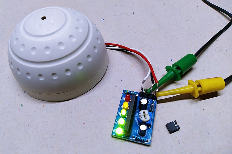
I bought a cheapo Chinese automatic LED nightlight a while ago. Working on this “automatic color changing night lamp” is pretty simple. A photoresistor (LDR) turns the LEDs on when it sees darkness and off when it sees lightness, with a bit proportional response in between i.e., during dimness.

Here’s its seller’s description:
- Input: AC 110-220V
- Power: ≤ 0.2W
- Light Source: Regular Yellow/Amber LED x2 + Colour Changing RGB LED x1
- Light Sensor: LDR
The color-changing RGB LED is of the slow-mode variety, which means it cycles at a rate of one color every few seconds.

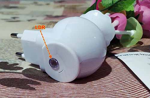
The photoresistor (LDR) is located at the bottom of the container. As you can see, it has a transparent protective covering on the front.
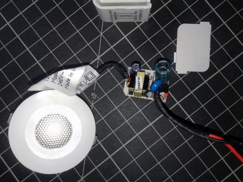
It’s very cheaply made, so of course, I wondered what it’s like on the inside. Thus, I decided to take a closer look at its internal electronics and figure out how it worked. Well, let me share my teardown story for you now!

The white front cover is surprisingly easy to remove. I just moved out two small screws on the back to pull it apart. Underneath, there’s a little circuit board with a single screw in the centre.
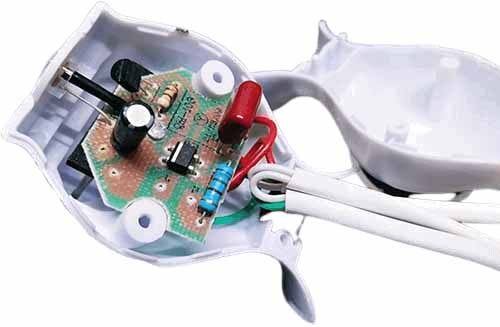
The first step was to figure out what everything was. That’s pretty easy as there’s only a few thru-hole components on the circuit board. Next, I traced out the circuit and prepared my own schematic for learning purposes.
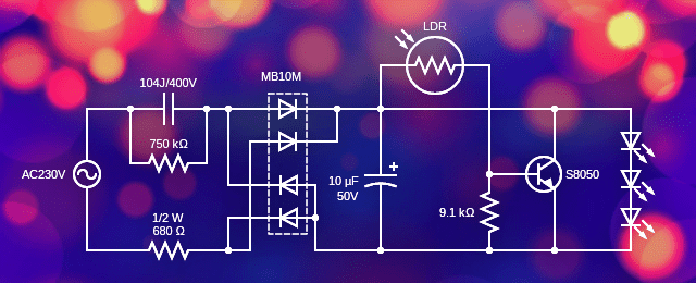
As you can see, this circuit uses a transformerless power supply for high voltage AC to low voltage DC conversion. The key component in the circuit is the 100nF/400V capacitor. For safety and to limit the inrush current a 680Ω ½ W resistor is used. The current flows right through the 100nF capacitor, which serves as a more-or-less 3.2KΩ ballast resistor. The large-value discharge resistor (750KΩ) in parallel with the 100nF capacitor will keep it from holding its high voltage and shocking the user when the nightlamp is unplugged.
Many years ago, I designed and publishes many automatic nightlight circuits similar to this. In my view, the only way to be absolutely safe with a non-isolated mains-powered circuit is to never come in contact with it. Luckily, this night lamp circuit has a plastic (nonconductive and nifty) enclosure.
Anyway, the 100nF capacitor can hold charge for a while and that’s why it should have a bleeder resistor across it. In this circuit, 0.1 μF x 750KΩ = 75ms, and you’re probably good to wait for a tick before touching anything inside the nightlamp.
After the capacitor, the AC input is rectified by a bridge rectifier MB10M, then filtered by a 10uF/50V electrolytic capacitor, and finally resulted in a constant current DC output. Since the “load” is somewhat constant, the low current output circuit hardly needs a zener diode (or similar thing) to limit the maximum voltage seen by the 10uF filter/buffer capacitor.
The LDR and the 9.1KΩ resistor forms a potential divider to switch the S8050 transistor on and off according to the light level detected by the LDR. So, when there’s amble ambient light, the S8050 transistor “shunts” the 10uF capacitor to turn the LEDs off and vice versa.
The maximum voltage measured across the 10uF capacitor is around 8.3VDC when all the LEDs are in on state. Note, those three LEDs are wired in series without a current limiting resistor, and as it seems, such a ballast resistor is not very crucial in this odd design.
Note at this point that since the same amount of current is passing through the circuitry whether the LEDs are on or off, this automatic nightlight eats up the same amount of power (0.2W) all the time. From the measurements made thus far, this nightlight has a power factor near 0 as expected, but making it questionable whether it meets mandated power factor laws.
And that’s all there’s to it. Now you can find your way to hijack this clever design with economic parts for your own purposes. Good luck and let me know how it turns out for you!
You have got the wrong circuit drawn. It will not work. The LED’s you put them in wrong position.
Nazmul: The schematic is 100% correct. If you are still in doubt, build it by following the given schematic and test it.
Moreover, many years ago, I designed and published many automatic nightlight circuits near-similar to this. Here’s a “printed” example https://www.electronicsforu.com/electronics-projects/nifty-night-lamp-diy
Nice write-up. Additional notes: At 50Hz, the 100nF capacitor’s impedance is about 32kohm, limiting the current to about 7mA. The high (230V) voltage and high (~32k) impedance act more like a current source than a voltage source. That’s why no current-limiting resistor is needed.
Circuit power is used in order of high to low by the LEDs (8.3V drop), the 680 ohm resistor (4.8V drop) and the diode bridge (~1.4V drop). The other resistors consume little power. So when the LDR circuit shorts out the LEDs, the power is reduced by about 50%.
@Mark: Thanks for taking the time to share your thoughts here. This will certainly complement this article to some extent. Since many capacitive-dropper power supply designs have already been shared here, I have intentionally omitted some theory parts and calculations in this post. Cheers, mark, see you later 👍