Lithium-ion (Li-ion) battery have cemented its position as the primary power source for portable electronics. One of the key benefits of a lithium-ion battery is that it have high energy density without being too bulky. If you have a project that needs a lithium-ion battery for energy storage, here’s one simple yet efficient add-on circuitry for you.
Described below is the do-it-yourself project of an inexpensive single-cell (1S/3.7V) lithium-ion (Li-ion) battery charger circuit principally designed for the cylindrical (18650) edition. The 18650 cells are one of the most prevalent types of lithium-ion battery cells. They are available from dozens of companies in hundreds of varieties, and their relatively belittled size and weight make them very conducive to power compact and portable electronics devices/projects.
Circuit Diagram: Tried and tested circuit diagram of the proposed solar/USB Li-ion battery charger is shown below.
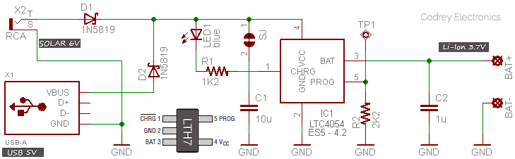
Circuit Description: The circuit is built around LTC4054ES-5 4.2 (IC1) complete constant-current/constant-voltage linear single-cell lithium ion battery charger IC from Linear Technology Corporation (www.linear.com). The IC is available in 5-lead TSOT-23 package with chip part marking LTH7. The given circuit allows charging from both a USB port (5V/500mA) and a solar panel (6V/500mA). There’s no harm in using a solar panel that can cater more current than the 500mA-limited USB port because the peak battery charging current (Ichg) is limited to about 450mA by the 2K2 (1%) charge current program resistor (R2). The 10uF capacitor (C1) is a Vcc bypass capacitor. The solder jumper (SJ1) allows the addition of an optional resistor in series with C1 to minimize start-up voltage transients caused by self-resonant and high Q characteristics of some types of ceramic capacitors. For more information, refer to official datasheet published by LT.
Similarly, the 1uF capacitor is added to reduce the ripple voltage incase there’s no battery connected at the output. Remember to use a tantalum capacitor for C2, but many types of capacitors can be used for C1. The blue LED (LED1) is a “charging” indicator that goes off when the charging cycle is completed i.e. just after the charge termination. The 1N5819 Schottky diodes (D1 & D2) are series blocking diodes to protect the electronics from reverse polarity voltage on Vcc rail.
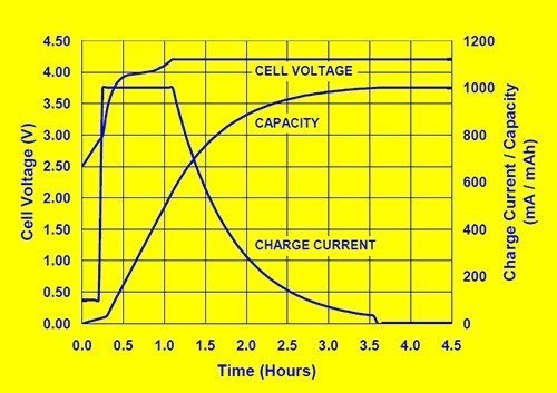
Li-ion Battery Charge Profile
When it comes to the preferred charge profile for Li-ion batteries, Li-Ion battery chemistries utilize a constant-current and constant-voltage algorithm that can be broken-up into four stages: trickle charge, constant-current charge, constant-voltage charge, and charge termination. Trickle charge restores charge to deeply depleted cells, and after the cell voltage has risen above the trickle charge threshold, the charge current increases in order to perform constant-current charging. Constant-current charge ends and the constant-voltage stage begins when the cell voltage reaches 4.2V. For charge termination, charge controller monitors the charge current during the constant-voltage stage and terminates the charge when the charging process when charge current diminishes in the range of 0.02C to 0.07C. There’s another charge termination method – the timer method – that determines when the constant-voltage stage begins and allows charging to continue for two hours, and then terminates the charging process (charger chip used here do not have the timer mode). Next figure depicts a typical Li-ion charge profile (reference – www.microchip.com).
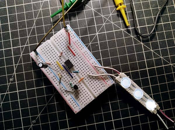
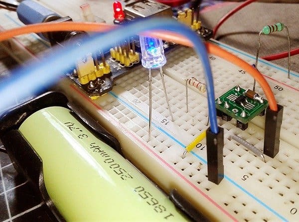
Circuit Construction
One MB-102 breadboard can be used for initial tests of the design as the total component count is very low. However, LTC4054 should be soldered on an SOT-23 adapter (with header pins) for ease of experimentation, and appropriate holder for the 18650 Li-ion battery is an absolute must. Lab tests can be carried out with an MB-102 breadboard power supply module (5V), or with a USB power bank (5V) as the dc power source. Keep all wire paths/tracks as short as possible to eliminate unwanted oscillations.
Key Components (used by author):
- R1: 1K2 ¼ w (5%)
- R2: 2K2 ¼ w (1%)
- C1: 10uF/50v (SMD, X7R)
- C2: 1uF/50v (SMD,X7R)
- D1-D2: 1N5819 (DO41)
- LED1: Blue (5mm, Vf = 2.8v)
- IC1: LTC4054 ES5 4.2 (TSOT-23, LTH7) – sunrom.com
- Test Battery: Li-ion (3.7V/2500mAh, 18650 with holder) – sunrobotics.com
- Test Solar Panel: 6v/3w (Monocrystalline) – amazon.in
Take note, the three-character code X7R is used for capacitors with Class 2 dielectrics. The X7R formulations are called “temperature stable” ceramics and fall into EIA Class II materials. Its temperature variation of capacitance is within ±15% from -55°C to +125°C, but his capacitance change is non-linear. Nowadays, X7R capacitor usage covers a broad spectrum of applications where known changes in capacitance due to applied voltages are acceptable.
And, here’s the technical specification of the 6v/3w monocrystalline solar panel used by the author:
- Voltage at maximum power (Vmpp): 6V
- Current at maximum power (Impp): 500mA
- Open Circuit Voltage (Voc): 7.2V
- Short Circuit Current (Iosc): 550mA
Ready for Production?
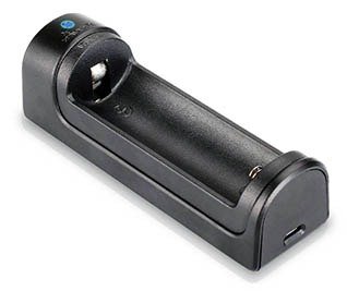
Naturally, a clever minuscule PCB design will let you integrate your charger board with a common 18650 battery holder. Or you can 3D-print your own pretty simple enclosure for the dreamed up commercial product (see the enclosure model below).
You can also increase the charging current to 800mA by shifting the value of R2 down to 1K25 (from 2K2) but you should use a good thermal PCB layout. Because of the small size of the TSOT package, it is very crucial to use a good thermal PCB layout to maximize the available charge current. The thermal path for the heat generated by the chip is from the die to the copper lead frame, through the package leads, (especially the ground lead) to the PCB copper, which is the heat sink. The footprint copper pads should be as wide as possible and expand out to larger copper areas to spread and dissipate the heat to the surrounding ambient. Feed-through vias to inner or backside copper layers are also useful in improving the overall thermal performance of the charger circuitry. TSOT package’s power considerations are discussed further in the applications information section of LT’s official datasheet.
Post-Production/Pre-Flight Test!
Here’s a setup for basic performance evaluation of the finished charger circuitry. Refer the easy evaluation equipment setup and follow the procedure below:
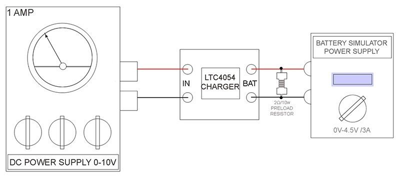
- Set the battery simulator (o-4.5V/3A) output to 0V
- Increase the output of dc power supply (0-10V/1A) slowly from 0V and ensure that the charger starts (its onboard LED lights up) when the input supply voltage exceeds 4.25V. Finally, set its output to 5V
- Raise the battery simulator output slowly from 0V to 9V, and then to 4.2V, and ensure that the onboard LED distinguishes (charge termination) at 4.2V
- Slowly lower the battery simulator output until it reaches 4.05V, and verify that another charge cycle is initiated (onboard LED lights up again)
That’s all for now!
Addendum: Pin 5 of IC1 can also be used to shut down the charging process, that’s why TP1 is added in the schematic to extend the functionality. The charge current out of pin 3 can be checked at any time by monitoring pin 5 voltage, as well.
Refer official LTC4054 datasheet for more – https://www.analog.com/media/en/technical-documentation/data-sheets/405442xf.pdf