Here’s a little audio amplifier project you can build from inexpensive and easily available parts. You can use this monaural audio amplifier even in any robotic project where you need to amplify audio signals. The design is based on the veritable tiny audio amplifier chip – LM386 – which can crank up common audio signals loud enough to drive a standard loudspeaker. This time I’d like to introduce and use a cheap LM386 module ideal for novices, rather than making it with discrete components.
LM386 Module Overview
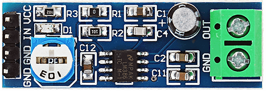
As you can see, the module is based on the SMD version of LM386 thus marked as LM386M (actually LM386M-1). The module has a power indicator and a volume controller in addition to the screw terminal for solder-free loud speaker connection. Likewise there’s a multi-pin male header for power supply and signal input connections. Now towards its specifications:
- Operating voltage: 5 V to 12 V DC
- On-board power indicator: LED (red)
- Volume Control: 10 K Ω Preset
- Signal Gain: x 200
- Recommended Speaker Impedance: 8 Ω
- Speaker Connector: Screw Terminal
- Power & Signal Input Connector: 4-pin Male Header
- Board Type: FR4 PCB
- Board size: 41 mm × 13 mm (approx)
It’s sure that the LM386M-1 in SOIC(8) package will work with supply voltage (vcc) up to 15V (maximum package dissipation 0.73W), and its recommended load impedance is in 4Ω to 32Ω range. With an 8Ω loud speaker, the typical output power is 325mW (at 6V). That’s okay but to verify the claimed features of the module we should need its circuit diagram for the detailed analysis.
LM386 Module Insights
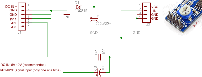
Here’s the verified schematic of LM386 module, borrowed from the web.
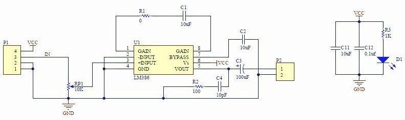
The 10uF capacitor (C1) wired between pins 1 & 8 of U1 sets the gain to 200 (46dB), so the claimed x200 signal gain is a decent statement. The resistor (R1) in the same path is a 0Ω one and a nice insertion indeed because by changing its value the gain can be set to any value from 20 to 200 whenever necessary. The 10uF capacitor (C2) connected at pin 7 is the bypass capacitor to improve PSSR (power supply rejection ratio) – a component usually dropped by most Chinese module makers!
As you can see, along with the 100uF DC blocking capacitor (C3), a Zobel Network composed of resistor R2 (100Ω) and capacitor C4 (10pF) has been used across the loud speaker output (pin 5) and ground (GND) terminals. This RC network provides a load for high frequency components of the amplified signal and quells high frequency oscillation effectively. I’ve not noticed an issue with the used RC values, it’s normally a 10Ω+47nF network, though. The 10μF and 100nF capacitors (C11-C12) between the VCC and GND power rails decouple the power supply. The 10μF capacitor filters low frequency noise while the 100nF capacitor filters high frequency noise.
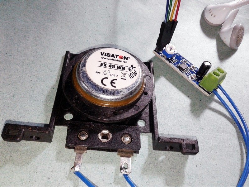
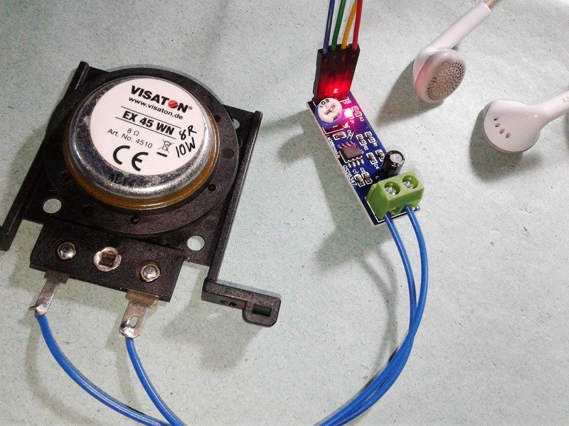
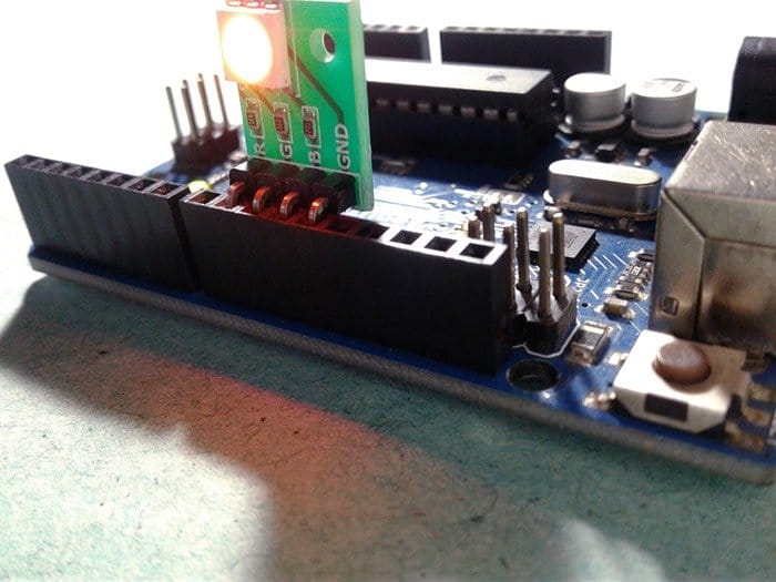
I tested my LM386 module (powered by regulated 5V dc adapter) with a Visaton EX45. On the whole, the module is a good choice as a functional and robust monophonic audio amplifier, and the one I received worked straight away without any problems (see casual snaps from my workbench).
However note that, LM386 in the module is configured for its maximum gain of 200x that has many drawbacks such as increased noise sensitivity, instability, and higher distortion.
Further the audio input section lacks the usual DC blocking capacitor what I consider to be sound is a 100nF one.
LM386 Module Adapter
After a number of thorough tryouts I’d developed a small adapter circuit for the LM386 module that’s actually nothing but a rude power and signal conditioner for plugging into the 4-pin header. If you wants to adjust the signal gain, then you will need to replace R1 with an external multi-turn trimpot. Or you can use a fixed 1K2 chip resistor instead of the 0Ω one to get around x50 gain. In addition one RC network (10K+33nF) can be placed between pins 1 and 5 to modify the gain and frequency response for specific applications like bass boost, preferably with a slide switch to switch the bass boost components in and out of circuit. Tested schematic of my LM386 module adapter is here:
Epilogue
This LM386 module will find some application as a general purpose audio amplifier on your work bench, but mainly I introduced it here as a learning experience for you and for the fun of it. Enjoy!
Hi, I’m trying to develop a headphone amplifier for my guitar but using this module a find out that it produce lots of distorsion. If there any modification that help me get a cleaner sound?
Im using a 9v battery as power suply and an acoustic-electric guitar.
Abel: Perhaps this post will help you to build a headphone amplifier for your acoustic guitar https://headwizememorial.wordpress.com/2018/03/17/not-just-another-headphone-amp-guitar-practice/
Also read https://hackaday.com/2016/12/07/you-can-have-my-lm386s-when-you-pry-them-from-my-cold-dead-hands/
Thank You!
Hi! i bought this LM386, hoping to make a lowcost baby monitor. you can consider me a beginner at electronics, but really interested in learning and building projects. i would like to know if i need any other components to make it work. In my mind, i only need this LM386 module, a 9v battery & connector, a speaker, a push button switch, and an electret condenser mic. Am i missing anything?
Thanks for your time reading my query. I’d really appreciate your help too.
Anna: Thank you for your interest in making a baby monitor. Now you can definitely build a basic baby monitor with the components you already gathered. Here is a link for your quick reference http://www.next.gr/audio/amplifiers/small-lm386-amplifier-l7403.html
Also if anything isn’t clear please let me know. Happy Making 👍