Turbidity sensors are widely used to measure the amount of suspended particles (turbidity) of the wash water in washing machines and dishwashers. In principle, turbidity sensor consists of an optical diode and optical transistor and measures the amount of light coming from the light sender to the light receiver, in order to calculate water turbidity. Despite the fact that it’s an extremely simple hardware arrangement, there’s not many easy-to-use turbidity sensors in the electronics market for hobbyists and makers. An upstanding turbidity sensor I found in yesteryear is the DFR Turbidity Sensor (SEN0169), easily obtainable in India too!
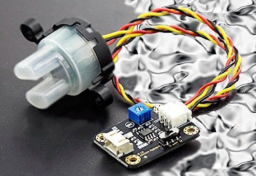
DFR Turbidity Sensor
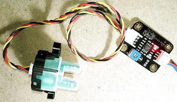
The DFR Turbidity sensor comprises of a sensor-head (liquid sensor) and an adapter module that provides analog and digital signal outputs. The encapsulated sensor-head is nothing but a combination of one light emitting diode and one phototransistor. Apart from the optical elements there’s a 470Ω fixed resistor (and a 1KΩ trimpot) to set operating current of the light emitting diode. Red wire coming out of the sensor-head is for positive supply (Vcc) and black is for ground (Gnd) while the yellow one is the signal (out) lead.
Maximum current required for the entire setup is about 40mA at 5V DC supply. Analog output range of the adapter is 0-4.5V while its digital output is merely a high/low level signal, threshold of which can be adjusted by one small 10K trimpot mounted on the adapter module. There’s also a small slide switch included in the module to select analog/digital output mode. In analog mode, the value of the output will decrease when in liquids with a high turbidity, and in digital mode you can alter the high/low trigger thresholds by tuning the onboard trimpot.
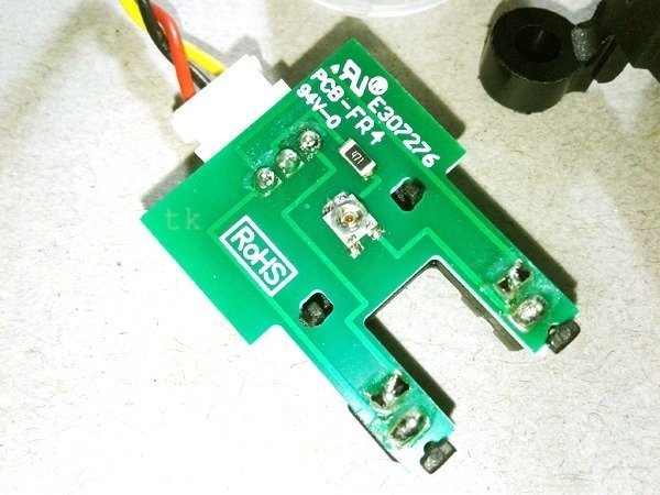
Below you can see a photo of the original circuit board placed inside the sensor-head (liquid sensor)
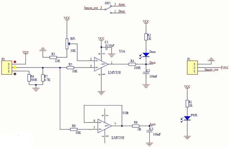
Here’s its circuit diagram (cooked by me)
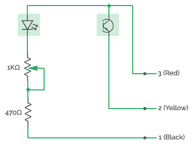
The adapter module of the DFR turbidity sensor is built around LMV358 IC. The LMV358 is a low-voltage (2.7-5.5V) dual-operational amplifier with rail-to-rail output swing. In the adapter, one-part of the LMV358 IC is wired as a comparator for plying digital signal output, and the second-part is used like a buffer for throwing analog signal output. Official schematic of the adapter is shown below for your quick reference.
For more, go to DFRobot’s product page https://www.dfrobot.com/wiki/index.php/Turbidity_sensor_SKU:_SEN0189
And/or jump to a primer authored by me in last year https://www.electroschematics.com/14077/diy-water-quality-meter-using-a-turbidity-sensor/
Good & Worthful?
Prices have gone up far too high, hence in India you may need to pay around `1000 for the online buy of one DFR Turbidity Sensor (https://www.fabtolab.com/gravity-turbidity-sensor). Personally I can’t afford to spend such a vast amount for a very simple sensor built with just two optical components and one op-amp (with the exception of a project funded by someone). An economical way is the use of an infrared LED and a phototransistor to build the sensor-head. Alternatively, you can pick any cheap optical fork sensor to divide it into light sender and light receiver components (see the reference drawing). And then do try an Arduino (or any other uC) for processing the analog signal output.
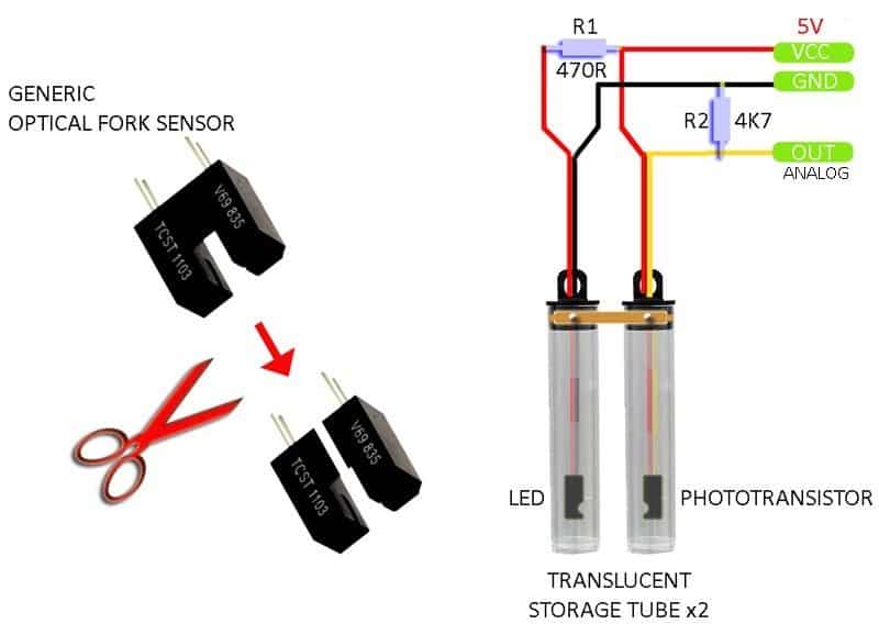
Note that turbidity is most commonly quantified by the Nephelometric Turbidity Unit (NTU), or the equivalent Formazin Nephelometric Unit (FNU). For testing the home-brewed turbidity sensor, first of all connect DC 5V between VCC and GND connection of the sensor-head, and measure DC voltage across the resistor R2 (between OUT and GND) when sensor-head is in clear water (0 NTU). After that, do another test in too muddy turbid water (3000 NTU) and note down the new voltage. Needless to say, another well-calibrated commercial turbidity meter (plus a precision dc voltmeter) is required for the evaluation process.
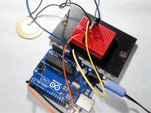
You can try your Arduino with a simple code to measure the output voltage as well. Connect VCC of the sensor-head to Arduino’s 5V, GND to GND, and OUT to AO to get readings on the Serial Monitor of Arduino IDE. The results will help you to make a reference chart for the mapping from output voltage to turbidity degree of water so that the required equation can be acquired credibly through curve fitting (curve fitting is the process of constructing a curve/mathematical function, that has the best fit to a series of data points, possibly subject to constraints – https://en.wikipedia.org/wiki/Curve_fitting).
void setup() {
Serial.begin(9600);
}
void loop() {
int sensorValue = analogRead(A0);
float voltage = sensorValue * (5.0 / 1024.0);
Serial.println(voltage);
delay(1000);
}
I hope you learned something from this article. Well, get ready to build your own Digital Turbidity Meter (DTM) using off-the-shelf components. I already completed an Arduino-based DTM experiment successfully, and much information is available through this website as a tested do-it-yourself project hereafter. Stay tuned!
Yes I agree that the commercial sensors are way too expensive. It is a simple IR led + sensor after all.
Sivaguru Mudaliar: I’m glad to note your comments and insight. Thanks!
Im trying to create a cheaper turbidity sensor for my university project, but im having many problems. I will give a shot for your ideia.
So where can I find these cheap sensors that you mentioned?
Im trying to use the dfrobot sensor inside a pipe, but it isnt working the same way it works outside, do you thing that the homemaid sensor will work better?
Gustavo Oliveira: The dfrobot turbidity sensor is not designed to fit inside a pipe. You may need another “flow line turbidity sensor” for your intended project. See this product https://www.awe-ltd.co.uk/products/turbidity/turbidity-sensor/turbidity-flow-sensor-tu810-910.html
The cheap optical sensor part I mentioned is available everywhere. I don’t know your exact location, but here I’m giving one link https://www.digikey.com/en/product-highlight/o/omron/prewired-slot-sensor-ee-sx-11-series
Good luck!
Im trying to use it to study the quality of the water that im receiving at my house. So i cut the pipe and put the waterproof shell inside it. I think it should be working the same way ita was.
I tried to build a sensor with a piece that i found in a printer, it is very similar to the one you mentioned in the post, but i had an issue to align the emissor with the receptor. How did you do this?
Did you really built your idea of a homemade sensor?
Thanks for helping
Another question
What does the led Dout in the sensor board means?
I saw in you project that yours is not on, in my case both led pwr and led Dout are on