Selfie Stick is a common smartphone accessory nowadays!
The word “selfie” first appeared in an online forum in 2002, and in 2013 it was named the Oxford Dictionary Word of the Year, defined as “A photograph that one has taken of oneself, typically one taken with a smartphone or webcam and uploaded to a social media website.”
Because of its increasing popularity smartphone makers need to be able to accommodate the accessory. So, there is now a plethora of accessories to help us get better images with smartphone cameras, including a stick dedicated to the individual and group selfie. Recall, selfie sticks are a popular smartphone accessory being inserted into the 3.5mm audio jack receptacle.
Believe me, I recently purchased a cheap wired selfie stick from an online store. I don’t really take selfies (pretty much just pictures of my electronics experiments) but I was curious to see how it was designed and what the electronics secrets inside it were. So, I decided to pick one up!
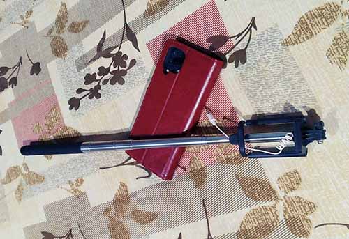
The selfie stick has a coiled microphone cable and a single camera button on its handle. The smartphone holder snapped into the telescopic arm of the stick swivels so that we can achieve an ideal angle for the camera. The solid rubber grip of the stick allows us to keep a secure hold on the stick while shooting and the camera button is ergonomically located. All in all, a pretty simple and useful photographic tool!
Note that today’s smartphone earphones are not just stereo speakers, but they integrate a microphone and a few user buttons. All these components are available through a 4-pin 3.5mm plug known as TRRS plug.
The common purpose of these buttons is audio/music control, but in general, their doings depend on the specific application. For example, if the smartphone camera is opened, the volume buttons can be used to take snaps. This idea is also the basis of popular wired selfie sticks.
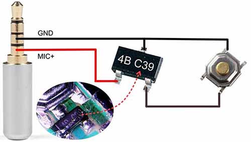
In principle, the selfie stick communicates a button press to take a picture in the same way a headphone accessory communicates a button press to adjust the volume. The selfie stick implements this button press by placing a mechanical switch between the microphone and ground lines of the audio jack. When the user presses the selfie stick button to take a picture, the smartphone recognizes the change in resistance between Ring 2 and the Sleeve of the 4-pole audio jack plug (see below).
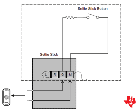
Not sure but roughly 240Ω +/- 1% button resistance is called for imitating the volume up function. Note that the microphone segment of the headphone jack triggers a picture once the circuit is closed by short-circuiting the GND (G) and MIC (M) wires, provided the button resistor is in the correct resistance range (210-290Ω).
More details https://source.android.com/devices/accessories/headset/plug-headset-spec
Obviously, this trick works only for Android since Apple devices demand custom circuitry to enable such functionalities.
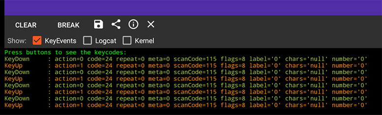
Now you can see that the selfie stick I used generates the “VOLUME UP” key code for Android (DECIMAL 24 / HEX 18 → VOLUME_UP).
Well then, I have a new toy, so what to do with it? Take it apart of course!
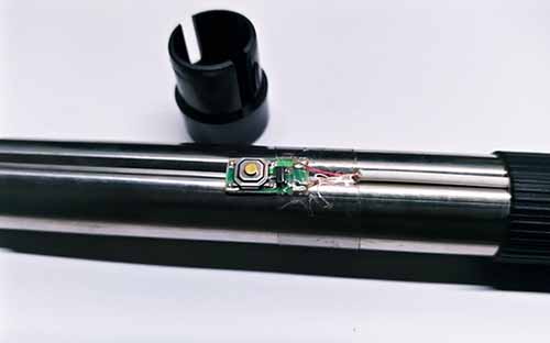
Now let’s see what’s on the stamp-sized printed circuit board.
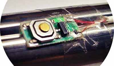
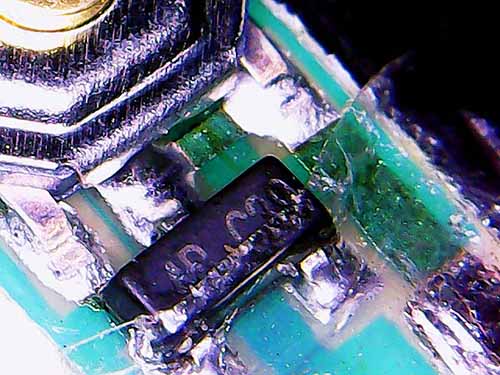
Here we see only a small chip part clearly marked 4B C39 other than the momentary push button switch. But what is it? To be honest, it’s a mysterious chip with no datasheets or clues to identify. On another selfie stick, I found a similar part, but it’s marked 540G!
After a lot of searching, research, and experimentation, I was completely disappointed! Unfortunately, it’s unclear what the SMD part (marked 4B C39) is. Might it be a proprietary chip to send shutter release button codes to both Android and iOS while pressing the selfie/shutter button?
Anyway, below is the selfie stick schematic I prepared for you!
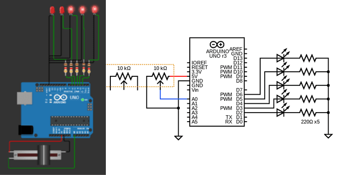
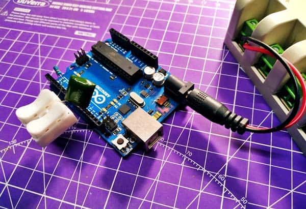
OK, let’s put a cheap selfie stick to work as something other than a vanity clicker! My idea now is to easily make my own enhanced remote smartphone camera trigger using a circuit board taken from an abandoned wired or wireless selfie stick or a remote camera shutter release button. More on this later.

That’s all for now! Let me know if you have any questions, comments, suggestions, or corrections. I hope you got something new from this post. Thanks for reading!
Hi T.K.
I’ve been trying to figure how to trigger the camera remotely, wasn’t even thinking about a 4-ring 3.5mm plug. I believe you will find the 4B C39 is a N-Channel JFET and the 540G is a N-Channel MOSFET. Really appreciate the article!
@John Golding: Welcome and thanks for your cheering feedback. Regarding the mysterious part, unfortunately it is still unclear what actually the 3-pin part is. It could be a FET of sorts, but I’m not sure. Hopefully we’ll figure it out soon. Have fun with your projects!