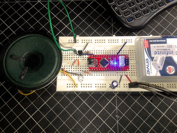
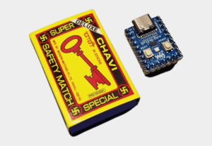
This post is about the construction of a multi-colored matchbox-sized magic lamp for kids using a simple and cheap microcontroller board. The most interesting thing about this build is that it does not require any external components other than the microcontroller board. Are you curious about how that’s possible? Here’re all the answers. Okay, let’s get started!
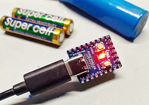
This little project uses the RP2040-Zero microcontroller board from Waveshare. Besides, only a USB power bank or a small battery pack is needed to complete the construction. Actually, my plan was to use a Digispark microcontroller board as the core part, but I accidentally switched to this amazing “Raspberry Pi Pico” microcontroller board. And, it’s definitely a fun experience!
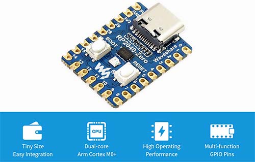
The RP2040-Zero is a little microcontroller board based on the Raspberry Pi Microcontroller RP2040. This stamp-sized module features a USB-C connector and a single WS2812B “NeoPixel” LED on board. It also has a “reset” button, aside from the “boot” button, which keeps it up to date and easier to use (https://www.waveshare.com/wiki/RP2040-Zero).
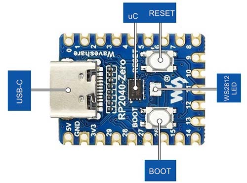
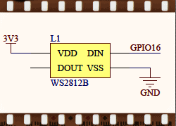
The WS2812B LEDs are individually addressable RGB LEDs with an integrated tiny microcontroller for each LED. Besides a common VDD and GND pin, there’s a single data line that goes from one LED to the next. In our RP2040-Zero board, regulated 3.3V is used to power the onboard WS2812B LED, and its data input (DI) is tied to GPIO16 of the RP2040 microcontroller.
So, the small form factor and the integrated lamp of this microcontroller board allow you to make a small magic lamp for children without using extra parts. If you have a little skill and patience, you can easily place the final build inside a matchbox-sized transparent or translucent box. Remember, the onboard reset button also plays a significant role in this fun project.
In this project, we’ll use a very simple code to run the WS2812B LED, but the following code can be tweaked to a certain extent to add more fabulous visual effects. I leave it to you!
import array, time
from machine import Pin
import rp2

NUM_LEDS = 1
PIN_NUM = 16
brightness = 0.5

@rp2.asm_pio(sideset_init=rp2.PIO.OUT_LOW, out_shiftdir=rp2.PIO.SHIFT_LEFT, autopull=True, pull_thresh=24)
def ws2812():
    T1 = 2
    T2 = 5
    T3 = 3
    wrap_target()
    label("bitloop")
    out(x, 1)               .side(0)    [T3 - 1]
    jmp(not_x, "do_zero")   .side(1)    [T1 - 1]
    jmp("bitloop")          .side(1)    [T2 - 1]
    label("do_zero")
    nop()                   .side(0)    [T2 - 1]
    wrap()


sm = rp2.StateMachine(0, ws2812, freq=8_000_000, sideset_base=Pin(PIN_NUM))

sm.active(1)

ar = array.array("I", [0 for _ in range(NUM_LEDS)])

def pixels_show():
    dimmer_ar = array.array("I", [0 for _ in range(NUM_LEDS)])
    for i,c in enumerate(ar):
        r = int(((c >> 8) & 0xFF) * brightness)
        g = int(((c >> 16) & 0xFF) * brightness)
        b = int((c & 0xFF) * brightness)
        dimmer_ar[i] = (g<<16) + (r<<8) + b
    sm.put(dimmer_ar, 8)
    time.sleep_ms(10)

def pixels_set(i, color):
    ar[i] = (color[1]<<16) + (color[0]<<8) + color[2]

def pixels_fill(color):
    for i in range(len(ar)):
        pixels_set(i, color)


BLACK = (0, 0, 0)
RED = (255, 0, 0)
YELLOW = (255, 150, 0)
GREEN = (0, 255, 0)
CYAN = (0, 255, 255)
BLUE = (0, 0, 255)
PURPLE = (180, 0, 255)
WHITE = (255, 255, 255)
COLORS = (BLACK, RED, GREEN, BLUE,YELLOW, CYAN, PURPLE, WHITE)


for color in COLORS:
    pixels_fill(color)
    pixels_show()
    time.sleep(1.6)

for color in COLORS:
    pixels_fill(color)
    pixels_show()
    time.sleep(0.8)

for color in COLORS:
    pixels_fill(color)
    pixels_show()
    time.sleep(0.6)

for color in COLORS:
    pixels_fill(color)
    pixels_show()
    time.sleep(0.4)
Be careful, MicroPython is whitespace-sensitive, so don’t remove the white tabs!
Okay, now paste or write this basic script in the Thonny IDE in your computer, and save it as “main.py” in your RP2040-Zero board.
Needless to say, you need a computer to run Thonny. You also need a good quality “USB-A to USB-C” cable for programming your RP2040-Zero board.
Once everything looks good, you can power your setup up through a USB power bank to get the color transitions of the lamp according to the code you uploaded/saved before.
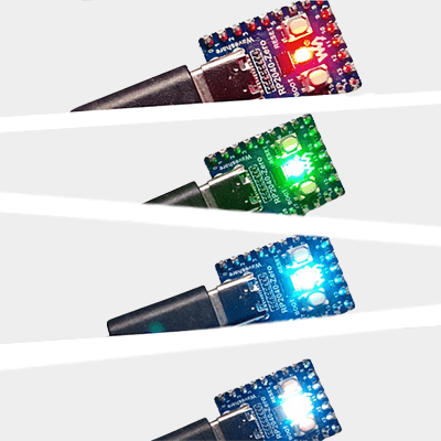
Note that the lamp starts in red and transits through all the predefined colors multiple times, but at different speeds in each phase. It’ll eventually remain white until the reset button is pressed (pressing the reset button will take your script to the initial point and it’ll execute it all over again from there). A little fun for the kids, that’s it!
Then, if desired, begin your own experiments with other colors and exotic sequences. Try it and have fun!
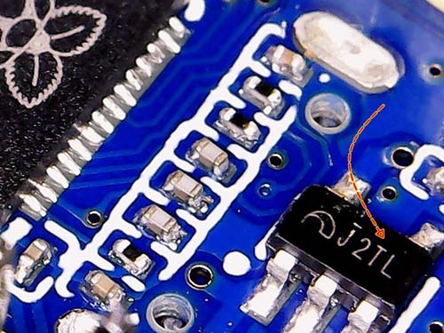
Now note that you can also use a 1S (3.7V) LiPo battery to run your setup. To do this, you need to connect the +/_ battery wires to the 5V and GND pins on the RP2040-Zero board respectively. Then, the onboard 3.3V LDO voltage regulator (see below) will do the rest.
Lastly, my build is not yet packed in a box as I wanted to improve my idea a bit. I hope sometime I’ll be able to do that and post updates here!