If you’re an active electronics hobbyist or maker, sometimes you may get a request from your close friend or neighbor to build a very economical table lamp or bedroom lamp for him/her but with some exquisite features. Of course you can fabricate one eye catching model by using a handful of locally available electronics components. But how to make it an over-the-top model?
It’s simple! Just try to include a touch-sensitive button interface in your blueprint so that the user can not only switch the light source on and off but also regulate the light output conveniently through a single finger touch. Again, that’s okay but how to incorporate such a complex feature in a cheap LED desk lamp design?
Recently I came across a similar situation, and urged on to work within a very poor budget. So there’s no means to try a bucketful of discrete parts or a bit costly microcontroller to fulfill the requirements. As you might guessed, the concept calls for a pulse width modulator and driver circuitry with a touch sensitive input interface. Not easy – so I banged my head on the work bench, and then took a coffee-break!
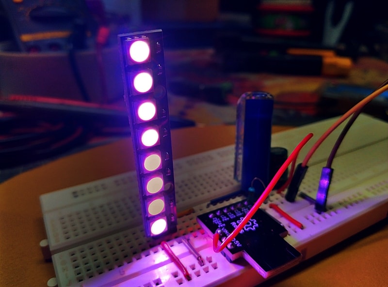
Few hours after that (in the middle of another work) I accidently got a cheap Chinese module from a junk box hived away but in an unnoted corner of my cupboard. It’s a good pick in right time indeed – the SGL8022W Touch LED PWM Module!
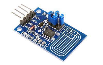
The SGL8022W Touch LED PWM Module (commonly known as FC-106 module) is a little module based on the SGL8022 single-channel DC LED control touch chip from SiGma Micro™ IC Solution Designing, China. SGL8022W is a single-channel touch chip for LED brightness regulation. This special chip can control the on-off state of LED lights and regulate its brightness on a continuous range, which could even be used on incandescent and halogen lights.
As can seen in the above photograph, the module has a 4-pin header for power supply input and signal output. There’s a pair of 2-way jumper headers with jumper caps to select a single mode out of four available modes as well (see next figure). Although the SGL8022W chip has a relatively wide range of input voltage, which could be chosen optionally within 2.4V to 5.5VDC, the module mentioned here is configured for 5VDC operation.
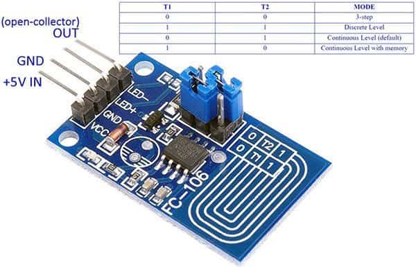
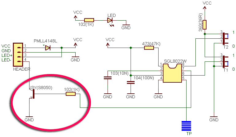
Surprisingly the module holds a J3Y NPN chip transistor (SMT version of the S8050 transistor) onboard, therefore we can directly drive a standard 1W star white LED i.e. without using an external driver transistor. All we needed is to route its anode lead to LED+ header through one 5.1Ω/ ½ w resistor, and cathode to LED- header. Then we can run the module with a suitable 5VDC power supply (5VDC/500mA will be a good pick).
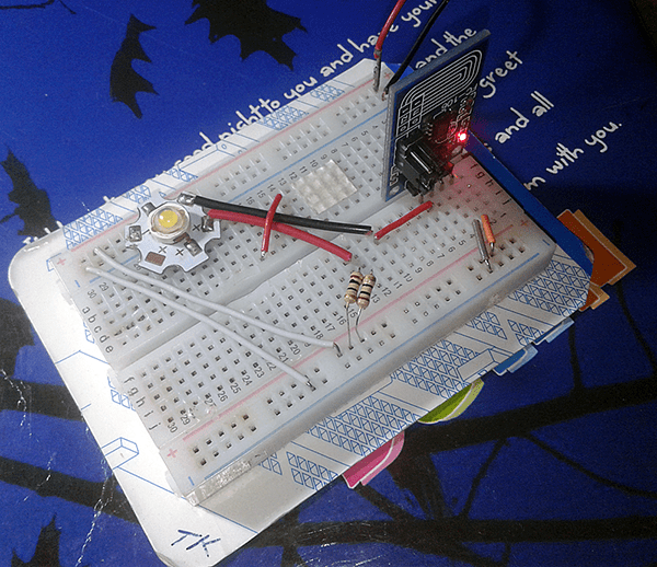
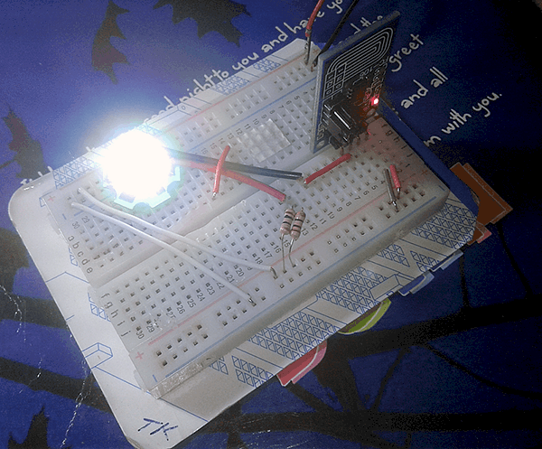
See, I used two 10Ω / ¼ w resistors wired in parallel instead of the 5.1Ω/ ½ w resistor because it’s only practicable at that time. A very happy outcome indeed!
Frankly my client’s playfulness surprised me as he also wanted an extra ‘power-socket’ in his final model to plug a white LED strip. Since he had in mind to get the cherished feature, and there’s no easy escape route in front of me, I simply wandered into some enhancement thoughts and eventually got hold of a likeable idea.
Power mosfets are most often used as switches where they are turned fully on or off to control electric loads such as high power LEDs and dc motors. Here we can use a P-channel mosfet for switching power to a ‘beefy’ load as a high-side switch which means it’s placed between the output load and the power supply voltage. As you can see in the below schematic, a P-Channel mosfet – IRF9540 – is connected with its drain connected to the load, and the source connected to positive rail of the power supply. The mosfet is turned on when driving the gate low relative to the source voltage and turned off by driving the gate toward the source voltage. The 10KΩ pull-up resistor (R1) on the gate will help to ensure that the mosfet (T1) will be kept in the off state when the SGL8022W module is powering up and its output is floating.
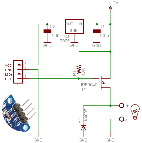
In the IRF9540 datasheet we can see that its RDS(on) is specified at -10V only, therefore it’s not a logic level mosfet and needs something close to 10V to drive it into saturation. This means a mosfet driver, transistor or some other circuitry is required to drive the gate with something close to 10V. Take note, VGS(th) is the gate threshold voltage at which the mosfet starts to conduct. Any voltage higher than this will drive the mosfet to the off state known as the cut-off region.

So the datasheet simply tells us that that to drive the mosfet into full saturation requires a VGS of -10V where the RDS(on) is 0.20Ω. Luckily, the open-collector S8050 transistor in the SGL8022W module can switch the gate at the source voltage of 12V to turn the mosfet completely off, hence obviates the requirement of an additional driver component.
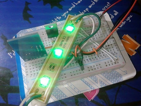
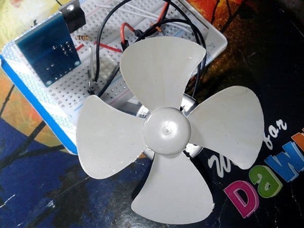
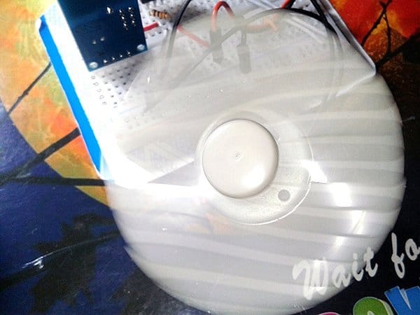
Back into my tries out, instantly after the breadboard build of the new ‘adapter’ circuit, I successfully tested it by powering a green 12VLED strip up. I also ran a lengthy test with one big dc motor fan with great success.
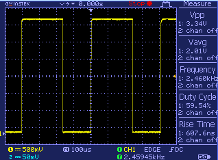
Here’s something that isn’t much discussed about, that I get a few doubts about. What’s the actual base frequency of the PWM here? So I took a scope test and observed that it’s around 100Hz-120Hz in most modes while running at 5VDC input, except in the 3-step mode where it’s about 2.5kHz. See the scope trace when it’s probed to the LED- header of the module, configured to run in 3-step mode when a 5mm red LED with its 680Ω series resistor get wired across the output headers (LED+ and LED-).
So, when coming to a conclusion, all 4 modes look good for both power LED and incandescent lighting, but the 3rd mode seems to be the right one for ‘step-speed regulation’ of the common DC motor based fan projects.
Next is the build of a retrofit capacitive touch switch for AC230V candent lamps. So, stick around to learn something new!
Here’s a bit easy explanation especially for those who want to know more about basic P-Channel Mosfet driving ideas. Keep reading for a how to use only positive voltage in this p-channel MOSFET tutorial https://www.baldengineer.com/p-channel-mosfet-tutorial-with-only-positive-voltages.html
hi there, such a nice project to do. Searched a lot about touch led dimmer and finally found your article. Thank you. Kindly help me out here i’m so new to this, can i have a clean wiring of this project. Thank you again
Rajkumar: Glad to hear. Thanks!
By the way, I didn’t understand your query right. you can see very clear circuit diagrams in the post itself. Check that. If you need further help,let me know what’s your actual requirement. I’ll be happy to help.
Hi, excellent article. I would like to drive a parallel strip of 0.2W LEDs with SGL 8022 Module . The load is 90 0.2W 2835 LEDs in Parallel driven at 45mA off a Mobile Phone charger on 2.4A. What are the additions I would have to do to use the SGL 8022 Module with dimming to get 45mA supplied to the LEDs.
Thanks and regards…Sundeep Shah
Sundeep Shah: Thanks 👍
As I can see, typical forward voltage (Vf) of a common SMD2835 0.2W LED is around 3.0-3.2V at the nominal 60-80mA forward current (If).
Since your idea is to connect 90 LEDs in parallel, the setup then demands an operating current of 45mA x 90 = ~4A on paper. Needless to say, you’ll need a 5V/4A+ power supply.
You can of course try the Power MOSFET idea explained in this post (https://www.codrey.com/wp-content/uploads/2019/12/Extra-Mosfet-Driver-Circuit.png) for your setup
after some tweaks.
First off, replace the IRF9540 in the given schematic with a logic-level PMOS such as NTD25P03L. Second, remove 7805 IC from the circuit and power both sections (SGL8022 module & LED driver) from the single 5V (>4A) power supply (Remember to add a suitable series resistor for the LED chain). Hope this helps.
Finally, If you think I took your question the wrong way, let me know!
Good afternoon TK, my name is ADRIAN and I’m a new hobbiest in electronic and the use of P-Mosfet. Thank you so much for your explanation. I replicated the project, but I had a problem with R1, because, when I turn OFF the ligths, after a few seconds, becomes to “flicker”, so I decide add two resistor more, and the problem dissapear.
Sorry about my English, I’m SPANISH spoken.
Adrian: Thanks for your interest in my post! I’m so glad you completed the project successfully. Always be creative and inventive! Good Luck 👍
Coming to the P-Mosfet issue, correct value of gate resistor will prevent self-turn-on but it might need some tweaks in certain cases, as done by you (Mosfet gate is exceptionally high impedance). This is a good post for your leisure read https://reibot.org/2011/09/06/a-beginners-guide-to-the-mosfet/
Once again, thanks for the inspirational feedback and for taking the time to share your thoughts that will be useful to other readers too 💛
sir i bought same module in order to make a study lamp for me but unfortunately iam not a engineer in electronics so i blow out 4 of them in the order to luminate 4v 1w+1w cob led please help me by giving an accurate list of components required and the schematic diagram of the circuit so i just only assemble them
abhishek: The schematic shown in this post is also suitable for driving high-power COB LEDs (https://www.codrey.com/wp-content/uploads/2019/12/SGL8022W-Module-Circuit-TK.png). So, your issues may be due to some other technical reason. Find it yourself.
abhishek: And, also refer this one https://www.codrey.com/wp-content/uploads/2019/12/Extra-Mosfet-Driver-Circuit.png