Let me introduce another simple do it yourself project, this time an electronics thermostat for residential electric water heaters. The circuit is designed for use in two-element water heaters in the upper position (upper thermostat), and is a good alternative to the time-tested “bi-metal” thermostats.
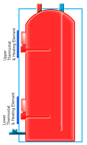
A Typical residential water heater has two heating elements, the upper and the lower elements, and the heating elements are controlled by upper and lower thermostats. Each heating element is connected to a thermostat to read temperature through side of tank wall and turn elements on and off. Note that both heating elements in an ordinary residential water heater are never work at same time. In the “non-simultaneous” models, upper thermostat is the main temperature controller!
Circuit Diagram
As can see in the circuit diagram, the design is centered around a few inexpensive yet fairly precise components. What at the heart is a popular 3-pin temperature sensor chip – the LM35DZ, (IC1) followed by a dual-comparator LM393 (IC2). An electromagnetic relay (RL1) plays the role of an isolated electric power switch to route AC230V to the connected heating element of the water heater. A multi-turn trimpot (P1) functions like the handed-down “mechanical thermostat knob” for adjusting water temperature range up within a pre-limited standard scale. Any regulated and clean 5V dc power supply can be used to run the entire circuit provided it’s capable of catering 150mA of current at the least. The LM35 temperature sensor provides an output of 10mV per degree Celsius, with an accuracy of 0.5°C at 25°C (the worse case accuracy, according to the manufacturer, is +/- 1 degrees C).
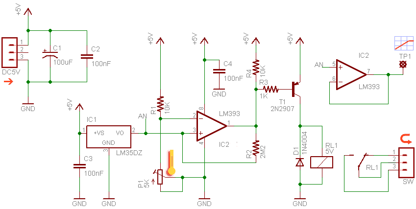
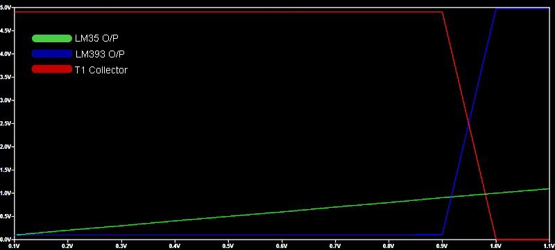
The LM393 (IC2) comparator works as described in the textbook and compares the input voltage received from LM35 (IC1) with the reference voltage (set by P1), setting its output high when the input voltage exceeds the reference voltage, and setting its output low when the input voltage falls below the reference voltage. The additional circuitry based on 2N2907 (T1) forms a simple electromagnetic relay driver, and a bit of hysteresis is provided by the resistor (R2) in the feedback path. This works as configured, with LM393 comparator’s output toggling between its high and low states whenever the input signal crosses the 1V mark (when wiper of the trimpot close to its mechanical centre position):
Note that the trimpot as a 5K multi-turn one, its maximum effective resistance is 2.5K (see how it wired) and this gives the thermostat knob a plentiful tour all the way through 0-100 degree C scale. However, keep in mind the recommended (and default) energy-efficient range setting is from 30 degree C to 60 degree C.
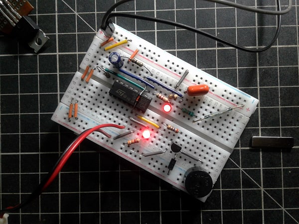
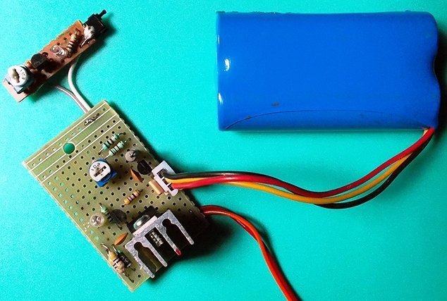
Construction Clues
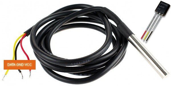
A small piece of perfboard is more than adequate as a base for the complete electronic circuitry. Naturally, a painted die-cast enclosure will give the thermostat a polished look. Unless the temperature sensor cable is going to be very short, a screened cable should be used or opt for a readymade (and water proof) LM35DZ temperature sensor probe (see below). In some situations the sensor chip hovers due to undesirable positive feedbacks, and a proven solution to the problem is the use of a parasitic stopper – one resistor in series with sensor’s output (never try to smooth the noise with a capacitor alone as it will upset the sensor chip).
Finally, second comparator of LM393 is wired to give an exact replica of the ‘raw’ analog voltage outputted by the temperature sensor LM35. Since it’s wired as a unity follower it completely isolates the temperature sensor from the external electronics circuitry (unity follower is merely a non-inverting amplifier with x1 gain). This analog output can be used to display the temperature level with the help of a suitable digital dc voltmeter or a small microcontroller-driven digital display panel!
(ref: waterheatertimer.org)