After posting the Backpack NeoPixel LED Safety Light project (https://www.codrey.com/arduino-projects/backpack-neopixel-led-safety-light/), I received a lot of requests to publish another do it yourself project based on regular light-emitting diodes, instead of using NeoPixel LEDs. So, I spent some time on such a simple design, here are the project details.
As usual, the real inspiration for this came from a commercial gadget, and honestly, this little project flexibly follows some of its cute features.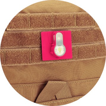
Before entering into the project, however, keep note that only the electronics of the theme is described here. That means you need to design and build your own printed circuit board (if necessary) and its enclosure to suit your actual needs and tastes. Well, get ready to make your own backpack LED patch with a handful of parts you can hopefully take out of your junk box!
I would like to use a different technique called Charlieplexing at this time for this project. You can see an old attempt of mine here https://www.electroschematics.com/arduino-charlieplexing/
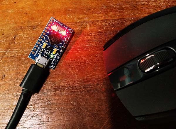
Also, I tried this idea with an Arduino Uno, but you can choose a smaller Arduino board (Lilypad/Pro Mini/Nano) because a larger board like the Arduino Uno is definitely not suitable for wearable electronics projects. Anyway, it’s up to you!
Charlieplexing?
Charlieplexing, first proposed in 1995 by Charlie Allen, is a technique that uses the tri-state logic capabilities of a microcontroller for driving a multiplexed display in which relatively few I/O pins on the microcontroller are used e.g., to drive an array of light-emitting diodes (https://en.wikipedia.org/wiki/Charlieplexing).
The project idea presented here relies on two properties that you may not have seriously considered before!
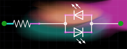
First, light-emitting “diodes” only pass electrical current in one direction. Therefore, you can use just two wires to control them if you connect a couple of LEDs together in antiparallel.
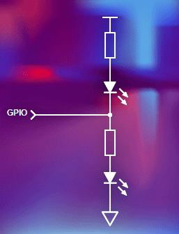
The second is the tristate logic (https://en.wikipedia.org/wiki/Three-state_logic) capability of the GPIOs of a microcontroller. So, a GPIO pin can be set as an OUTPUT (H/L) pin or treated as an INPUT pin. When you change a GPIO to input mode, that pin shifts to a high-impedance (Hi-Z) state and stays there until reverted. Note, Hi-Z refers to an output signal state in which the signal is not being driven. The signal is left open so that another output pin can drive the signal or the signal level can be determined by a passive component.
Actually, there’re numerous tricks that can be used to drive multiple LEDs when you are short of GPIOs on your microcontroller. I won’t get into that right now, perhaps in a separate post later!
Backpack LED Patch/Hardware
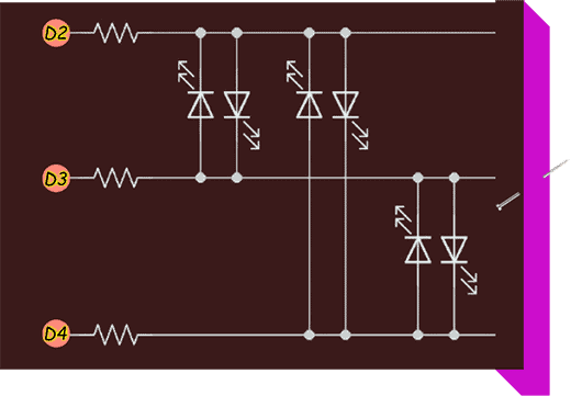
Below is the hardware setup diagram for the Arduino (Uno/Nano) Backpack LED Patch. Check out it to see how everything is connected.
Backpack LED Patch/Software
Below is the example code/sketch for the Arduino (Uno/Nano) Backpack LED Patch.
#define SCAN_DELAY 600

byte LEDS[] = { 2, 3, 4 };
const byte LED_COUNT = sizeof(LEDS);
void setup() {
}

void loop() {
  for (int i = 0; i < LED_COUNT; i++) {
    for (int j = 0; j < LED_COUNT; j++) {
      if (i != j) {
        pinMode(LEDS[i], OUTPUT);
        pinMode(LEDS[j], OUTPUT);
        digitalWrite(LEDS[i], LOW);
        digitalWrite(LEDS[j], HIGH);
        delay(SCAN_DELAY);
        pinMode(LEDS[i], INPUT);
        pinMode(LEDS[j], INPUT);
      }
    }
  }
}
Backpack LED Patch/Quick Test
Well, let’s see how charlieplexing is fulfilled in practice!
Here we’re driving six LEDs with just three GPIOs of Arduino. Note, the LEDs need to have similar characteristics to be able to drive all of them with a delighting brightness. Also, you’ll need one current limiting resistor per GPIO employed here (3×330Ω for example).
In principle, you can drive n*(n-1) LEDs using n pins. This is the number of ways of selecting 2 items out of n different items.
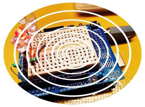
Below you can see my quick test setup (Arduino Uno + Uno Proto Shield + 5mm Red & Blue LEDs + 330Ω Resistors).
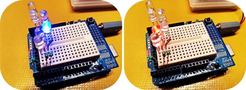
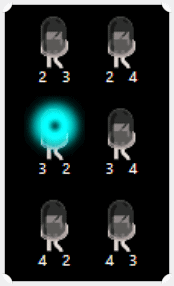
The code controls each LED (turns it on and off for a moment) in cycles. You can arrange the LEDs as shown below (source of inspiration https://wokwi.com/playground/charlieplexing)
Going Further…
Now you know you can drive a bunch of LEDs from a few microcontroller ports through a less common trick, and save those precious ports for something more sensible. Say thanks to charlieplexing!
I could imagine several variations on fabricating this. You could use any kind of Arduino with pretty much the same source code – obviously, you’d need to tweak the codes. You could also use a lower or higher number of regular LEDs or an LED matrix.
Not to mention, a fancy case would be nice. Perhaps something 3D printed that lets you clip onto your backpack. By this point, note that an appropriate hook and loop backing allows the device to be attached to any Velcro-compatible material.
Finally, this is just a little project to fill some time. Have Fun!