You may often see the musical instrument Melodica on stage shows. From Wikipedia (https://en.wikipedia.org/wiki/Melodica) melodica is a small, light, and portable free-reed instrument similar to the pump organ and harmonica. It has a musical keyboard on top and is played by blowing air through a mouthpiece that fits into a hole in the side of the instrument. Pressing a key opens a hole, allowing air to flow through a reed. The keyboard usually covers two or three octaves.
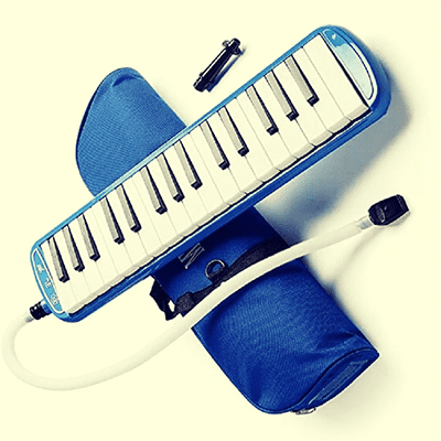
Oh, this post is not about making a melodica, but just to share the details of a funny blow switch project. Okay, let’s get started…
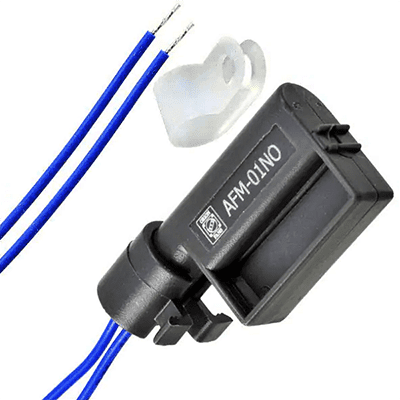
What you see above is the photograph of an airflow monitor (AFM) from Orion Fans (https://orionfans.com/productFiles/datasheet/AFM.pdf). The air-flow monitor provides a simple alternative to indicate positive or negative airflow of fans and blowers. When properly installed and connected in series with an optical or audible signaling device, a bi-directional switch will activate an electrical contact if the airflow of the fan falls below 8.2 ft/s, turning the signaling device on or off. The AFM monitor can also be attached to an existing plastic grill or guard.
Although we can use regular airflow monitors and pressure sensors/switches cleverly in many hobby electronics projects, they’re often very expensive or not readily available. So, now let’s think about how to do that in a tricky way. And, consider this blow switch project only as a little example.
Blow Switch DIY
A blow switch can be usually activated by either sucking or blowing into the switch. So, blow switch is ideal for those who’ve very limited movement as it allows the user to suck or blow into the mouthpiece (comes complete with a washable saliva trap) to activate a call on the nurse call system.
Fortunately, you can build a pretty simple blow switch model by following these steps (I agree there’re many other ways as well):
First of all, buy a “water purifier pressure switch” from your trusty online seller.
These pressure switches usually have three different types of switching contacts – normally open (NO), normally closed (NC), and changeover (SPDT). Since the changeover type has both NO and NC contacts, it can be employed easily in a wide range of projects.
Note, a mechanical pressure switch should not be confused with a pressure transducer because a pressure transducer converts pressure into an electrical output signal. On the other hand, a mechanical pressure switch simply operates an integrated electrical switch at a preset pressure level.
In short, all of the components of a mechanical pressure switch are located inside the switch case, and it has one inlet pressure port. The inlet pressure pushes a piston against a spring that has a known resistant force. Then, the piston triggers the micro-switch, moving it between normally closed (NC) and the normally open (NO) position through an operating pin and an insulated trip button – the NC contact will open, and the NO contact will close.
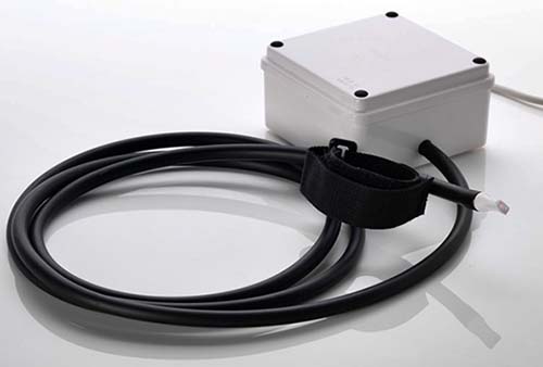
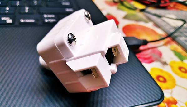
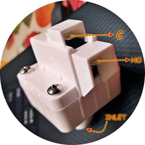
Below you can see the photograph of the RO water purifier low-pressure switch I got from an Amazon seller. As you can see, accessing the third terminal (NC) of the changeover switch (SPDT) is a bit hard, but it’s not needed normally. In fact, it’s trimmed by the manufacturer (or seller) because the device can be sold as a high-pressure switch (HPS) or low-pressure switch (LPS) through that dirty trick (more on this later).
A couple of links to get an overview of pressure sensors commonly used in RO (reverse osmosis) water purifiers:
- Low-pressure switch for RO water purifier PS-M21L
- High-pressure switch for RO water purifier PS-M21H
Since the contacts of a common RO water purifier low-pressure switch are normally in open state, and it changes to a closed state when there’s enough pressure (higher than the threshold level), we can use it as the sensor for our blow switch (a gentle blow-through will close its contact for a while, that’s enough).
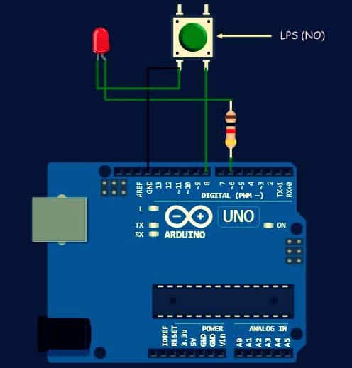
Now you know what’s going on, therefore next to do is to connect the low-pressure switch (LPS) contacts (C and NO) between an I/O pin and GND rail of an Arduino. Then put the I/O pin into input mode, and pull the pin up internally. So, when the switch is ON the I/O pin is grounded and thus will read LOW, when the switch is OFF the internal pull-up asserts the pin HIGH when read. The Arduino series of microcontrollers opens up a new world of great possibilities for novice programmers and hobbyists. That’s why an Arduino setup is preferred here over using traditional analog circuitry.
My Arduino Sketch example enables the pull-up resistor for the low-pressure switch I/O pin so you would not need to add an external pull-up resistor in your design. Simply allow the low-pressure switch to drive its l/O pin LOW to announce it has been activated. You can use any of the available I/O pins you wish for your design and modify the example code accordingly to add more features!
int delay_value = 1500; // Heartbeat Indicator Slow Flash
int led_pin = 6; // Annunciator LED Output D6
int sensor_pin = 8; // LPS Input D8

void setup() {
pinMode(led_pin, OUTPUT);
pinMode(sensor_pin, INPUT_PULLUP); // Internal Pull-up Enabled
}
void loop() {
  digitalWrite(led_pin, HIGH);
  delay(delay_value);
  digitalWrite(led_pin, LOW);
  delay(delay_value);
  int sensor_state = digitalRead(sensor_pin);
  if (sensor_state == LOW) {
    delay_value = 150; // Event Notification Fast Flash
  } else {
    delay_value = 1500;
  }
}
This code makes the LED wired to D6 pin of Arduino Uno blink faster when a gentle blow is detected by the LPS (low-pressure switch) connected to D8 pin of the Arduino Uno. Note that, in idle state, the same LED blinks at a slow rate endlessly.
The delay() function keeps the LED on and off for 1500ms during every iteration of the loop() function. As the loop() function is perpetually repeated, this code will turn the LED on and off repeatedly in idle state. However, when a gentle blow is detected, the code changes the delay value and makes every iteration last for only 150ms.

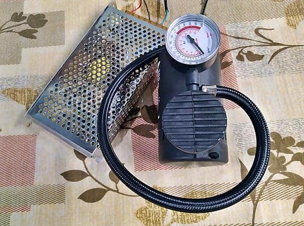
First, I tested my Arduino setup with a portable tyre inflator and then tested its performance again by blowing air through the inlet of the low-pressure switch. Everything worked as expected!
Finally, the WokWi simulation link of this project https://wokwi.com/arduino/projects/307690966577316416
That’s all for now. Give this experiment/project a try for yourself. Please be reminded, this post is prepared for you to try and learn. You’re urged to improve the basic concept for a better real-world application!

excellent article, will check it out and have a go.
Grahame Skate: Thank you so much for your inspiring feedback. Good luck on your project ✨