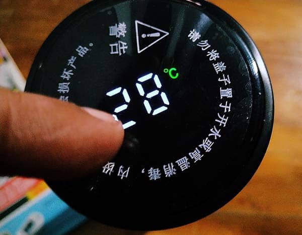
Quite recently I got a stainless-steel vacuum flask with a digital temperature readout integrated on its top lid. When I touch the top of the lid it simply displays the inside temperature of the container for a while. Really interesting!
Naturally, I took inspiration from that design and designed another temperature indicator with a tricolor LED display. In this post, you will see the details of that little project. Okay, let’s get started!
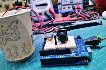
This design is nothing more than a multi-color temperature indicator that changes the color of its display from green to yellow (and to red) as the temperature increases. You can use it as a nice temperature indicator for coffee mugs, facial steamers, etc.
You will need a few commonly available parts to do this project as listed below:
- DS18B20 Digital Temperature Sensor (waterproof version)
- Arduino Uno (or Nano) Microcontroller Board
- 10mm Red, Yellow, Green LEDs or RYG Traffic Light LED Module (see notes)
- 4K7Ω, 220Ω, 330Ω ¼ W Resistors
More about RYG Traffic Light LED Modules https://www.codrey.com/electronic-circuits/traffic-light-led-modules-lets-start/
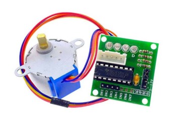
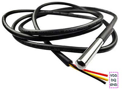
The DS18B20 waterproof digital temperature sensor usually comes with a 90-100 cm long cable, with the temperature sensor inside a stainless-steel tube at one end and three flying leads at the other end. This gently sealed digital temperature sensor probe lets you precisely measure temperatures in wet environments with a simple 1-Wire interface. Since the DS18B20 provides 9 to 12-bit (configurable) temperature readings over a 1-Wire interface, only one wire (and ground) needs to be connected from a microcontroller.
The pinout for this DS18B20 waterproof temperature sensor probe is as follows:
- RED=VDD
- BLACK=GND
- YELLOW = DQ (DATA LINE)
Now see its key features:
- 0-5.5VDC input voltage
- Waterproof
- -55°C to+125°C temperature range
- ±0.5°C accuracy from -10°C to +85°C
- 1-Wire interface
In addition, the DS18B20 sensor can derive power directly from the data line (parasite-power mode), eliminating the need for an external power supply. Also, each DS18B20 sensor has a unique 64-bit serial code which allows multiple DS18B20s to function on the same 1-Wire bus.
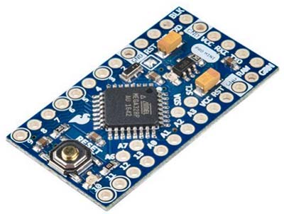
Although an Arduino Uno (or Nano) is recommended here, you can use the Pro Mini (5V/16MHz) edition because it has an extremely small form factor. But you have to keep in mind that Pro-Mini (https://www.sparkfun.com/products/11113) does not have an onboard FTDI chip like the Uno/Nano so you would need to buy a separate FTDI breakout board for USB interfacing with your computer but after you upload the code you can remove it unless you need serial communication!
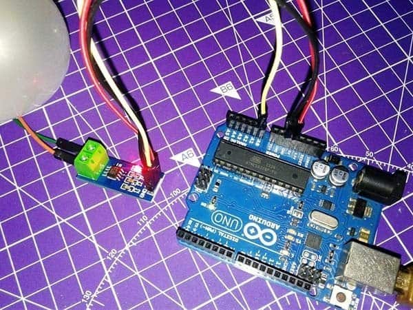
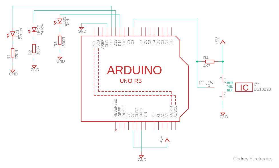
Getting back into the project, below you can see the hardware setup diagram. If you are using the RYG traffic light LED module instead of three different LEDs, the first three resistors (R1-R3) are not required.
Next, you should copy-paste the following code in your Arduino IDE. But first, you must add the required libraries and then upload the code. You can download the “One-Wire” and “Dallas Temperature” libraries thru these GitHub links:
- https://github.com/PaulStoffregen/OneWire
- https://github.com/milesburton/Arduino-Temperature-Control-Library
#include <OneWire.h>
#include <DallasTemperature.h>

int greenLedPin = 13; // D13 to Green LED
int yellowLedPin = 12; // D12 to Yellow LED
int redLedPin = 11;  // D11 to Red LED

int temp_sensor = 8; // D8 to DQ of DS18B20

float temperature = 0; // Variable to store the temperature value
int lowerLimit = 35;   // Define the lower temperature threshold
int upperLimit = 40;   // Define the upper temperature threshold

OneWire oneWirePin(temp_sensor);

DallasTemperature sensors(&oneWirePin);

void setup(void) {
  Serial.begin(9600);

  //Setup I/Os as OUTPUT
  pinMode(redLedPin, OUTPUT);
  pinMode(greenLedPin, OUTPUT);
  pinMode(yellowLedPin, OUTPUT);

  sensors.begin();
}

void loop() {
  Serial.print("Requesting Temperatures from sensor: ");
  sensors.requestTemperatures();
  Serial.println("OKAY");

  temperature = sensors.getTempCByIndex(0);

  digitalWrite(redLedPin, LOW);
  digitalWrite(greenLedPin, LOW);
  digitalWrite(yellowLedPin, LOW);

  Serial.print("Temperature is ");
  Serial.print(temperature);


  if (temperature <= lowerLimit) {
    Serial.println(", Green LED is ON");
    digitalWrite(greenLedPin, HIGH);
  }
  else if (temperature > lowerLimit && temperature < upperLimit) {
    Serial.println(", Yellow LED is ON");
    digitalWrite(yellowLedPin, HIGH);
  }
  else if (temperature >= upperLimit) {
    Serial.println(", Red LED is ON");
    digitalWrite(redLedPin, HIGH);
  }
  delay(1000);
And then, you may try to improve your prototype by adding new functionalities/features to my crude code. For example, you can add some lines to employ an alarm function when the temperature is high.
At this time remember that the DSB18B20 measurement at full 12-bit resolution takes around 750ms. For faster measurements (near 100ms) the resolution can be reduced in 1-bit steps down to 9-bit. With the library used, it’s easy to set the resolution for 9-bit, but we will stick to the default 12-bit resolution as speed is not a big concern here.
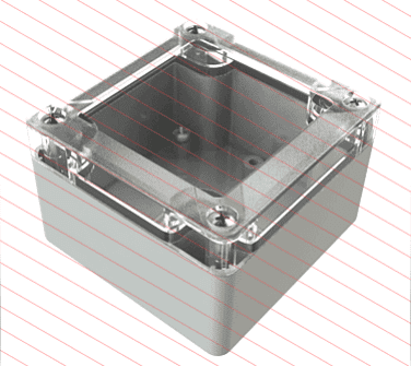
To finish off, you only need a battery pack, and a translucent shell to put your prototype in. The enclosure size depends on the Arduino board you used (you can use plexiglass and a laser-cut machine to make your own project box).
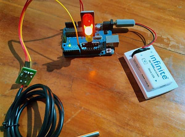
For the battery pack (500mAh minimum), a 2S LiPo (7.4V nominal) battery will be a good choice (Or you can a 9V USB rechargeable Li-Ion battery).
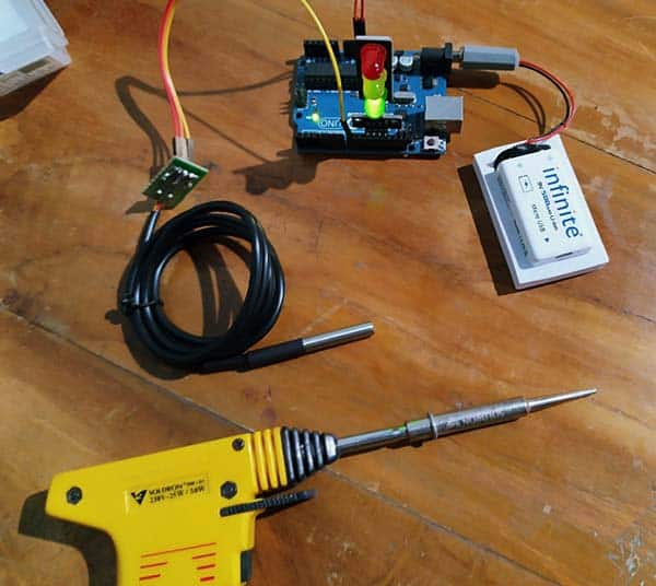
Finally, this is another casual snap of my quick test assembly. That’s all for now. See you next week!