Nano Digital Volt Meter is a microcontroller based simple DIY project for electronics hobbyists and makers. It is a compact digital voltmeter which can incisively measure input dc voltages in 0 to 55V range. The project is built around an Arduino Nano microcontroller board. Another key component is an I2C LCD panel, which is easier to wire up as the microcontroller can talk to the display over a single pair of wires.
Key Hardware
- Arduino Nano (v3)
- 16×2 I2C LCD
- 1K &10K (1%) Resistors
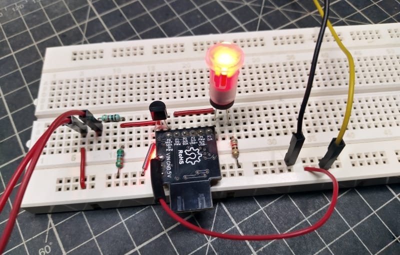
Wiring Diagram
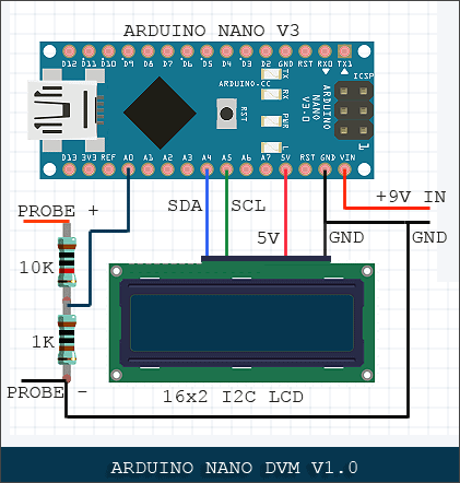
The analog sensor on the Nano board senses the voltage on the analog pin and converts it into a digital format that can be processed by the microcontroller. Here, the input voltage is routed to an analog pin through a simple passive voltage divider, and with the values shown it can measure dc voltage in 0V to 55V range. However, when feeding 55V, the analog pin will be held at its maximum tolerable voltage of 5V. So, it’s better to treat this voltmeter as a “0-48V DVM” unless you want to add an “Arduino Toast” in your breakfast menu!
Arduino Code/Sketch
/*
* Nano DVM
* Version v1.0
* With 16x2 I2C LCD
* Designed as a 0-55V DC DVM
* Recommended Input 0-48 V (see text)
* By - T.K.Hareendran
*/
#include "LiquidCrystal_I2C.h"
#include "Wire.h"
#define LCDADDR 0x3F // Select correct I2C address of the I2C LCD (0x27 or 0x3F)
//#define LCDADDR 0x27 // Uncomment for next address, and comment above line!
#define LCDCOLS 16
#define LCDROWS 2
LiquidCrystal_I2C lcd(LCDADDR, LCDCOLS, LCDROWS); // LCD object
void setup() {
lcd.begin();
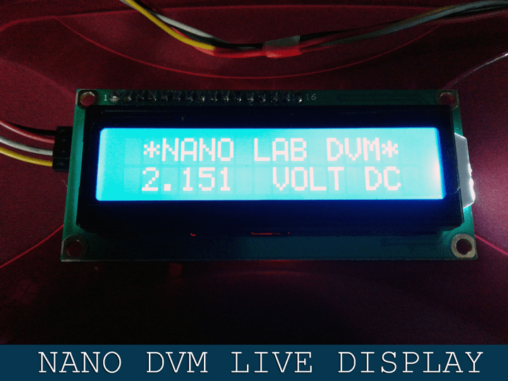
lcd.print(" *NANO LAB DVM* "); // Custom Text
}
void loop() {
int Pin; // 0-1023 I/P
double Vin;
Pin = analogRead(A0); // Probe Input
Vin = Pin * (5.0*11 / 1023); // Pin to Vin (Reduction Factor 11)
lcd.setCursor(0, 1);
lcd.print(" ");
lcd.setCursor(1, 1);
lcd.print(Vin, 3);
lcd.print(" VOLT DC "); // Custom Text
delay(500);
}
Power Supply Picks
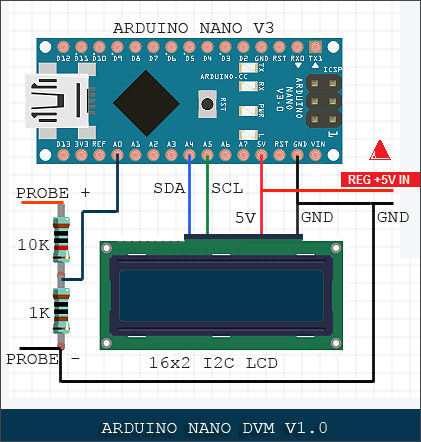
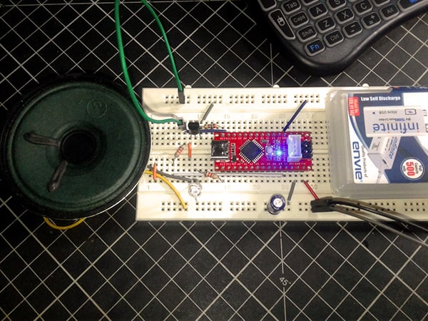
The Arduino Nano can be powered from any 7-12V unregulated dc supply through Vin pin (pin30). You can also use a regulated 5V (> 5V inputted here will fry your board at once) instead as the power supply by applying +5V pin (pin27). According to official documentation, the input power source (USB/Vin/+5V) is selected to the highest voltage source automatically.
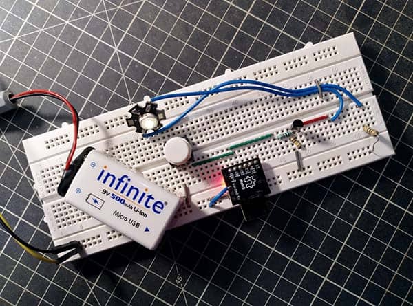
The prototype was tested initially with a Duracell PP3-size 9-volt alkaline battery. Since the +5V pin of Nano can provide safe current upto 500 mA, the LCD was powered directly from the same +5V (pin27) rail. However, it’s better to use a regulated 5V external dc power supply for the DVM (see figure shown below) if you prefer to use the display with always-on backlight.
And finally, a random snap of my Nano DVM’s display screen:
Hi sir, thanks for sharing the schematic and code. I had tried the project and it worked very well.
Sijo Mathew: Congrats! Happy to hear that you made it successfully. Thank You!
Hello thanks for sharing – works like charm
a little question tho…
lets say i’m using mega board – can i probe like multi sources?
lets say A0- 15v , A1- 13v , A2- 28v and so on
Osher: Glad to see your feedback. Thanks!
Yes, you can probe multiple sources even with an Arduino Uno. Here’s a primer – https://startingelectronics.org/projects/arduino-projects/arduino-4-channel-LCD-voltmeter/
Needless to say, Arduino Mega offers more I/O lines, more sketch memory and more RAM, thus gives plenty of room for your ideas. Give it a good try.
Further, I’ll come up with an Arduino + OLED multi-channel”DVM/Datalogger” project within a couple of weeks. So please stay tuned. Good luck!
Hi i also measure voltage using arduino nano however the coding was failed. Can you help me?
Syam: It’ll work! What’s the error message dellivered by your prototype? Could you elaborate how your code failed – upload failure or voltage reading error? Also post relevant screenshots here. Otherwise it’s not easy to figure out the issue.
failed compiling code.
Arduino: 1.6.5 (Windows 7), Board: “Arduino Pro or Pro Mini, ATmega328 (5V, 16 MHz)”
Codreydotcom_version_singlechannel.ino: In function 'void setup()':Codreydotcom_version_singlechannel:17: error: no matching function for call to 'LiquidCrystal_I2C::begin()'
Codreydotcom_version_singlechannel.ino:17:11: note: candidate is:
In file included from Codreydotcom_version_singlechannel.ino:9:0:
C:\Program Files\Arduino\libraries\LiquidCrystal_I2C-master/LiquidCrystal_I2C.h:58:8: note: void LiquidCrystal_I2C::begin(uint8_t, uint8_t, uint8_t)
void begin(uint8_t cols, uint8_t rows, uint8_t charsize = LCD_5x8DOTS );
^
C:\Program Files\Arduino\libraries\LiquidCrystal_I2C-master/LiquidCrystal_I2C.h:58:8: note: candidate expects 3 arguments, 0 provided
no matching function for call to 'LiquidCrystal_I2C::begin()'
This report would have more information with
“Show verbose output during compilation”
enabled in File > Preferences.
@Pat: Sorry, but I couldn’t figure out the snippet you pasted here!
Check your LCD version or the display is not proper. I removed the LCD and using the Serial.print for output until I send it over to another device.
no matching function for call to :
LiquidCrystal_I2C::begin()
Thomas Jenkins: Thanks for your reply. I’m glad you have responded to the reader’s comments. And it’s a great suggestion.
BTW now I’m playing with the “New-Liquid Crystal” Library (https://github.com/fmalpartida/New-LiquidCrystal).
no matching function for call to :
LiquidCrystal_I2C::begin()
installed the library but still having this error
Ski: It looks like a different “LiquidCrystal_I2C” library is being used than the one my code was written for.
As mentioned before in another reply, I tried this code before 3 years, naturally using a library. which’s quite popular at that time!
So, you can try installing this old library https://github.com/fdebrabander/Arduino-LiquidCrystal-I2C-library.
And, delete other similar libraries installed. Hope this helps!
Change begin to init as that library does not accept the begin command but uses the initiate command instead
Sean: Now I’m sure it’s a problem of the library you have currently in your Arduino library folder. Note that actually there’re multiple libraries available with the same name “LiquidCrystal_I2C.h”, and an easy fix is to install the correct/required library and delete existing I2C 16×2 LCD libraries.
Since this project was posted about 3 years ago, I have no clear idea which library I was using at that time. I recently reinstalled my Windows and Arduino IDE, as well. Anyway I will try to test this again in my spare time.
Can i send the measure values over ethernet? Or serial?
What HW and additional code is required
@M.B: Yes, possible. But I haven’t tried it yet (may be come up with one later). Now you may check out this link to get a basic idea http://www.skillbank.co.uk/arduino/logging.htm Thanks!
Author’s Update: I’m glad many readers are still showing keen interest in my simple DVM project that’s published years ago. Thanks everyone!
Sadly, new libraries do not seem to support my old code, because I’m constantly getting feedback on errors occurred while compiling the Arduino Sketch.
Fortunately, I found that this library (https://github.com/fdebrabander/Arduino-LiquidCrystal-I2C-library) works well with my published code.
So download and give it another try (also remember to delete similar new libraries installed earlier).
I tested it again and you can see a screenshot here – https://www.codrey.com/wp-content/uploads/2021/12/Codrey-DVM-Code-Library-Issue-Resolved.jpg
Finally, stay tuned for my updated DVM project.
The theory behind this is understandable for me but one thing that confuses me is how you determined 48V was the highest (and safest voltage) to measure? Why not 49V or 47V, or any other values for that matter?
I would imagine that it would be just as fair to say that 50V would be the maximum safe voltage input for the arduino. What was the process behind determining these maximum voltage ratings?
Erick: It’s clearly explained in the second paragraph of this post!
Can I use this to measure the output voltage of my 36v dc motor ?
This setup basically works like a 0-48VDC digital voltmeter. So, you can!
Also, its input range can also be changed by changing the potential divider (10K/1K). Read the article again. Thanks!