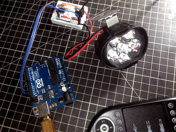
There are many ways to use standard hobby servos in do it yourself projects. I semi-regularly hear about design concepts that I’m not familiar with. Recently, I had a reader, who’s an amateur toy maker, inquire about building a simple light-sensitive servo actuator. I’ve never been asked that before, so I did a little research and eventually came up with a basic model. Recently, the reader recreated my project and used it to move the head of a toy owl according to the intensity of the ambient light. Now you can make it too!

At this point, I’ve chosen an Arduino Nano v3 microcontroller to drive a Tower Pro SG90 micro servo according to the intensity of the light falls on a GL5528 LDR (photoresistor).
In many cases, the SG90 9g micro servo seems to be the go-to solution for driving small/lightweight actuators. After all, it’s a commonly available cheap 180° hobby servo suitable for a wide range of applications, including radio-controlled toys and robotics, or just to have some fun with whatever crazy project we’re working on.
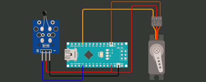
The diagram at bottom shows the typical Arduino Nano v3 based hardware setup. While this can work, heedful analysis and component selection is demanded to achieve a system with good performance and long-term reliability.
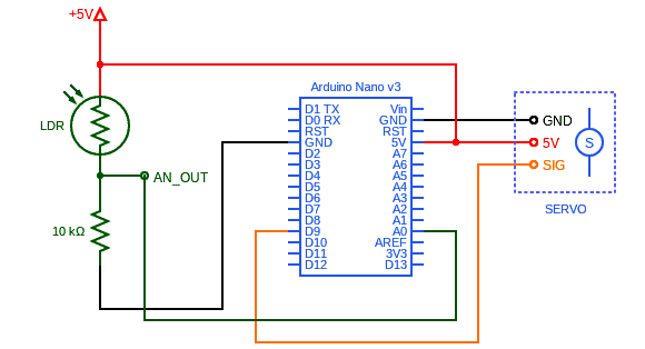
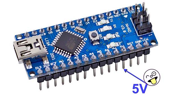
Keep in mind that you can power up the Arduino Nano v3 setup by using any USB charger or USB power bank. You can also power up it through the Vin pin on the Arduino Nano board, but remember that the input voltage must not exceed the safe voltage limit of the Arduino Nano v3 that is 12V and the minimum voltage for Vin is 7V. Another method is using the 5V pin of the Arduino Nano v3. In this case, you must use a well-stabilized 5VDC power source.
Before proceeding it’s worthwhile noting that, it’s not a good idea to power the servo from the 5V pin. In some cases, it may work, in others it may fry the microcontroller board. But if you’ve a decent 5VDC power supply you can connect that to the servo and to the 5V pin and power both of them. I successfully managed to power the above shown hardware setup through the 5V pin with 4xAA 1.2V NiMH batteries and everything runs fine. Give it a try!
With the intent of sweeping the servo with the microcontroller, I made an elementary Arduino Sketch as shown below. The code is extremely simple and self-explanatory.
#include <Servo.h>

Servo lightservo;

void setup() {

  lightservo.attach(9);
}

void loop() {

  int lightValue = analogRead(A0);

  lightValue = map (lightValue, 0, 1023, 0, 180);
  lightservo.write (lightValue);
}
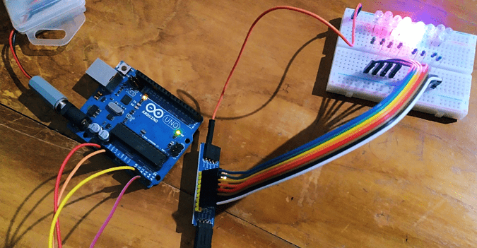
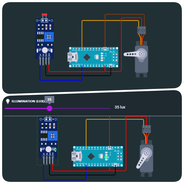
In the first iteration, I went from paper circuit to breadboard, and the resulting prototype worked well. Then I went back to the beginning and started with a mock-up simulation in WOKWi (https://wokwi.com/projects/343341271246438996) to give the aforenamed reader a quick online demonstration. Since the simulator does not offer any discrete photoresistors as yet, analog output of a generic LDR module was used for that simulation (see below).
This post is a mere introduction to different ways of controlling standard hobby servos using Arduino. But don’t stop here. There is a lot to explore – for instance, using a thermistor to make a temperature-sensitive servo horn.
Well, now it is your chance to get involved, and develop something awesome. Are you up to the challenge? Good luck!