Welcome to the lovely sound of analog electronics!
Now I’m building some white noise and pink noise generators for an upcoming amateur audio project. In this article, you can see a few basic design ideas as a result of those experiments. Nevertheless, I’ll be doing some more work with this concept, so keep an eye out for a future post on the subject.
What’s White Noise?
In principle, white noise is random noise that has a flat spectral density, that is to say, the white noise has the same amplitude, or intensity, throughout the 20Hz to 20kHz audible frequency range. White noise is so named because it’s analogous to white light which is a blend of all visible wavelengths of light. Since white noise includes all audible frequencies, it’s often used to mask other sounds. Personally, I’m using a homemade white noise machine as a sleep aid to drown out annoying noises in and around my bedroom at night (https://www.electroschematics.com/arduino-white-noise/).
White noise is also used extensively in the audio electronics domain for making electronic music. For example, white noise is used there typically to recreate percussive instruments such as cymbals and snare drums which have high noise content in their frequency domain (https://en.wikipedia.org/wiki/White_noise).
White Noise Generator!
Okay, I like to experiment! First off, this is a pretty minor revision. Like so many old designs, this one also depends on noise inherent in an NPN transistor between its emitter and base. For the build I tried a whole bunch of transistors – nothing significant, simply what I had in the junk box. The basic schematic looks like this:
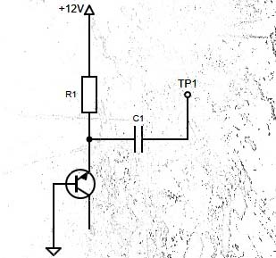
Although not pointed in the above schematic, I ended up using the good old BC107B transistor. But since every transistor has a different breakdown voltage and every transistor will render different noise quality, selection of this component will require some research on your part. Nothing special, but I also got moderate results with my favorite general-purpose NPN transistors 2N4401 and 2N2222.
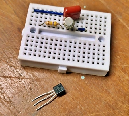
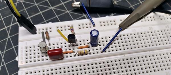
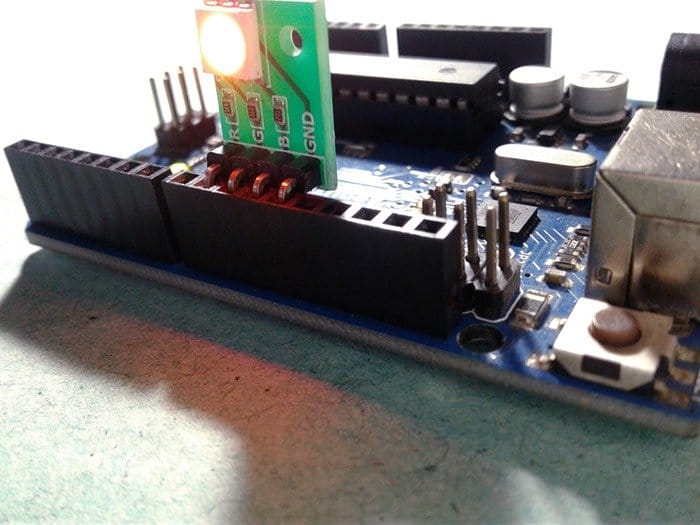
Below is an early snap of the above circuit in development on a mini breadboard.
My random picked BC107B with 470KΩ resistor (R1) on regulated 12VDC gave noise levels above 100mV peak-to-peak. Note that the resistor value is also not set in rock, and it’s worth experimenting with!
The output was measured at the test point TP1 (C1 = 100n). The probing after the 100n coupling capacitor was intentional but only to see how the noise would look when ac coupled.
This is enough for a simple standalone white noise source, but you need to buffer and decouple the signal output (ac coupling to remove the dc offset).
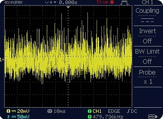
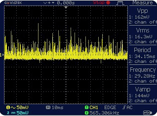
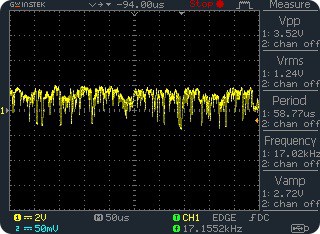
So, the basic scheme is slightly revised. I decided to make the revision using discrete components only as it’s simple and works with a single-rail power supply. Anyway, you could use an op-amp ICs instead for the amplifier stage. Also, note that the value of the resistor R1 is changed t0 33KΩ from 470KΩ through empirical observations. In the below oscillogram, you can see the signal at the emitter of the BC107 transistor is around 150mV from its highest to the lowest point. It thus appears that the revision has a bit better output, certainly good enough for the noise-making work.
The next image shows the modified schematic of the white noise generator. If you choose your components wise, then the output should be good and strong enough for further experiments.
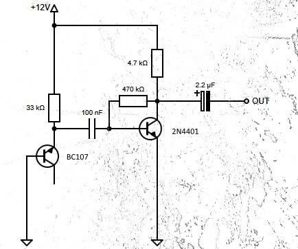
With the components shown, the final output of the common-emitter amplifier was around 3.5V p-p, might be rich enough for testing with a signal tracer or audio amplifier (if one doesn’t have an oscilloscope). Anyway, never follow this crude design blindly. You should do your homework to get the best from your build, which I won’t detail.
The common-emitter amplifier transistor 2N4401 has the base bias resistor (470KΩ) connected between the collector and base leads. This significantly improves the bias stability for hFE changes which’s certainly an improvement over the fixed base bias method. If you want to read more about common-emitter amplifier biasing techniques, this would be a good guide https://www.vintage-radio.com/repair-restore-information/transistor_biasing.html
A little break now…
Upcoming is an analog white and pink noise generator project for those who like to experiment. The idea strictly follows the same popular analog trick – a white noise source followed by a -3dB/octave lowpass filter. But you will have to wait a while as I am still looking for some essential analog parts that are out of hand. Waiting is not always a bad thing. It can bring its own joy – the thrill of anticipation!

Thank you very much for this circuit. That’s the first of 4 circuits that I’ve tried that actually works. I am building a random number generator with it. I’ve used 2N2222 transistors because that’s what I have in stock. The minimum voltage at which the circuit produces noise is 9V, under which it acts as an oscillator, which I found interesting. I plan on using a step-up DC-DC converter to get 12V so that I can use a 9V battery while having some margin. I have not noticed any difference by using a 1µF capacitor instead of the 2.2µF one, but replacing the 33k resistor by a lower value made a difference in some scenarios where the oscillation would not start. I do not have an oscilloscope unfortunately, but I use a 1W amplifier+speaker combo to hear the results. My only issue with that is that I cannot measure the output voltage. Anyhow, thanks again!
@Jimmy Gervais:
Thanks for the inspiring words and feedback. Glad you’re enjoying my posts and still along for the ride. Cheers!
BTW here’s another post you might find interesting http://www.kerrywong.com/2014/03/19/bjt-in-reverse-avalanche-mode/