Assume that you’re in the middle of a microcontroller-based project with a big array of sensors and transducers ready and waiting to get their I/O allocation by the microcontroller, and sadly you found yourself there’s not enough fill for the can. In similar situations you can try an external analog/digital multiplexer/demultiplexer chip with your microcontroller as it can help you expand the I/O pins when you’re running out of pins!
The HP4067 Analog Mux Module
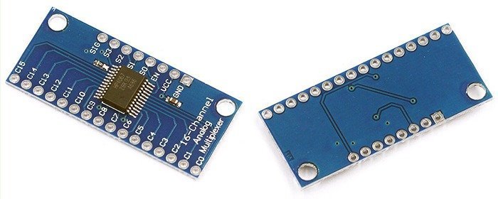
A multiplexer (mux), in principle, merely acts as a single-pole multi-through rotary switch that allows you to control the flow of one pin to many others usually in either direction. For this primer, I’m just going to utilize the quite popular 16-channel analog multiplexer/ demultiplexer HP4067 (CD74HC4067). Nowadays you can buy cheap Chinese modules/ breakout boards based on HP4067, and it’s extremely easy to connect with your microcontroller. The module actually works as a 16 to 1 switch. The digital switch inputs (S0-S3) can be used in a binary style (0-15) to determine what channel (Co-C15) the “SIG” is connected to. Also, there’s an enable (EN) input to enable/disable the channels i.e. pulling it up to VCC will disable all channels, and pulling it down to GND will enable all channels. Much easier, right?
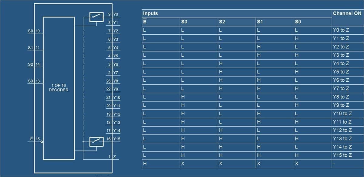
To simplify things, bringing all 4 switch pins LOW (0) would switch the module to channel 0 (so SIG and C0 would be linked), bringing them all HIGH (1) would move it to 15 (so SIG and C15 would be linked).

To recap, the “SIG” pin connects to any of the 16 available channels. When you write a binary code to the switch pins (S0 – S3) the corresponding channel (C0 – C15) is selected. For example, by writing 1001 to S3 S2 S1 S0, the C9 channel gets connected to the “SIG” pin. At first, it may seem complex, but not. Below is a quick reference table for those who doesn’t feel binary comfortable.
| S3 | S2 | S1 | S0 | SIG + |
|---|---|---|---|---|
| 0 | 0 | 0 | 0 | C0 |
| 0 | 0 | 0 | 1 | C1 |
| 0 | 0 | 1 | 0 | C2 |
| 0 | 0 | 1 | 1 | C3 |
| 0 | 1 | 0 | 0 | C4 |
| 0 | 1 | 0 | 1 | C5 |
| 0 | 1 | 1 | 0 | C6 |
| 0 | 1 | 1 | 1 | C7 |
| 1 | 0 | 0 | 0 | C8 |
| 1 | 0 | 0 | 1 | C9 |
| 1 | 0 | 1 | 0 | C10 |
| 1 | 0 | 1 | 1 | C11 |
| 1 | 1 | 0 | 0 | C12 |
| 1 | 1 | 0 | 1 | C13 |
| 1 | 1 | 1 | 0 | C14 |
| 1 | 1 | 1 | 1 | C15 |
Quick run on Arduino
The HP4067 module seems like a funny thing, that’s usual but never underestimate the power of the multiplexer chip resting at its core. It’s in fact a pretty smart digitally-controllable SP16T bidirectional switch. From what you’ve read, I understand that you have no problems playing your HP4067 module with Arduino. There could be a lot of things that you can do with, however, this time I’m giving only a few ‘starter’ hints.
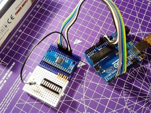
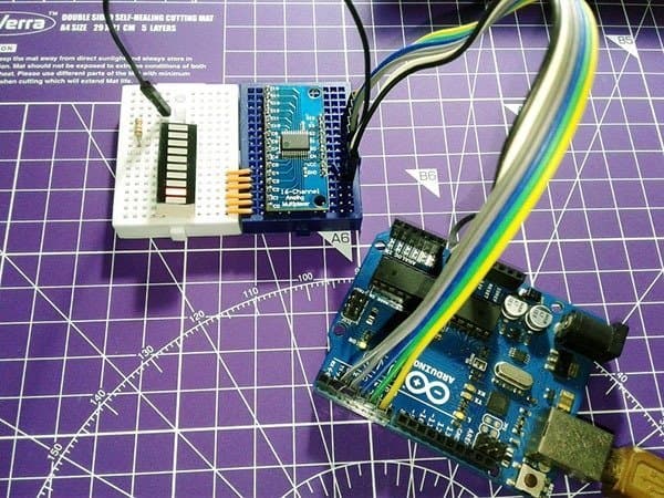
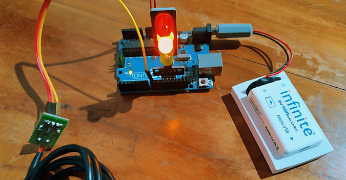
For the quick run experiment, apart from the HP4067 module, you’ll need an Arduino Uno and 16 LEDs (or an LED bargraph display like the one used by me). The following code just lights up the LEDs, one after the other, with a small delay. Just to make it less cluttered, I used only 6 LEDs (out of 10) in the bargraph display with single 1K2 current limiter resistor (see the quick test video).
/*
 * HP4067 (16-Channel Analog Multiplexer/Demultiplexer) Module
 * Quick Test with Arduino Uno & LED Bargraph Display
 * Adapted Experimental Sketch (thanks to arduinolearning.com)
 * Authored By T.K.Hareendran/2019
 * Published by codrey.com
 */

const int channel[] = {2, 3, 4, 5}; // S0,S1,S2,S3
 const int outputPin = 6; // SIG

void setup()
{
for (int arduinoPin = 2; arduinoPin < 7; arduinoPin++)
  {
    pinMode(arduinoPin, OUTPUT);
  }
}

void loop()
{
  //Iterate through C0 to C5 of the multiplexer
  for (int muxChannel = 0; muxChannel < 6; muxChannel++) // Number of LEDs wired
  {
      muxWrite(muxChannel);
    digitalWrite(outputPin,HIGH);
    delay(500); // 500 milliseconds delay
  }
}

void muxWrite(int whichChannel)
{
  for (int inputPin = 0; inputPin < 4; inputPin++)
  {
    int pinState = bitRead(whichChannel, inputPin);

    digitalWrite(channel[inputPin],pinState);
  }
}
Note that here the “SIG” pin (D6) of the Arduino is configured as a simple output pin. Anyway, you can proceed with a PWM signal by configuring the “SIG” pin as an analog output pin and then calling the write method and providing as arguments the channel number and value (0-255) for the duty cycle of the PWM signal. The “MUX74HC4067” Arduino library will help you to grab more and more practicable ideas, so make yourself clear and then go to https://github.com/pAIgn10/MUX74HC4067.
Table given below depicts the recommended hardware interconnection:
| HP4067 Module | Arduino Uno |
|---|---|
| GND | GND |
| VCC | 5V |
| EN | GND |
| S0 | D2 |
| S1 | D3 |
| S2 | D4 |
| S3 | D5 |
| SIG | D6 |
You should add one LED per multiplexer output i.e. wire the anode of first LED to C0 and the sixth LED to C5. Then route cathode of each LED to GND through a 1K resistor (total six resistors). Again note that the given code is prepared for fewer LEDs, so if you want to use more LEDs, change the code as necessitated.
Random snaps from author’s workbench:
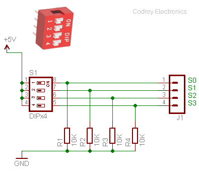
Quick test with a DIP Switch
If you don’t have an Arduino board handy, you can still use a standard 4-position DIP switch to manually select/control all switch inputs (S0-S3) of the 4067 multiplexer module. Here’s one basic idea of an active high DIP Switch configuration i.e. if a switch is closed/on, the signal will be connected to power (state = H), and if a switch is open/off, the signal will be connected to ground (state = L) through the resistor.
That’s all folks. I hope you enjoy this little primer, and if you have any comments or suggestions you can use the comments box below. Happy Multiplexing!
Thanks for the guide. It’s very informative. Do you know if this would multiplex AC signals (-2v to +2v) as well? I’m thinking of multiplexing 16 current transformers (after burden resistor) by tying one of their legs to each other and feeding the other 16 legs to this multiplexer. Then adjusting the output of the multiplexer via a bias circuit to bring the voltage to 0-4v and feeding it into an Arduino or Raspberry PI analog input and using a multiplexer like this seems like the easiest thing to do if I don’t want to build 16 bias stages which may interact with each other.
@Ross: I’m not sure, but I’ll find out and let you know.
Frankly, I already know something about certain “dual-supply” multiplexers like the MAX4508 (https://datasheets.maximintegrated.com/en/ds/MAX4508-MAX4509.pdf) but I’m not sure if they’re the right pick for your project. It’d be nice to know more about them. Thank you for your note, and best wishes!