Some time ago I was asked by a voracious reader to design a simple steam sensor switch for him. The purpose of the steam sensor switch was to turn on an electric switch when the moisture level on the steam sensor pad raises above a certain threshold, that’s pretty straightforward, and I built a minuscule circuit to do the job.
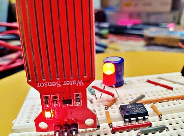
The crude analog steam sensor in this circuit is nothing but a cheap water sensor module. When humidity on the active face of the water sensor rises, the output voltage will also go up. Simple, yeh?
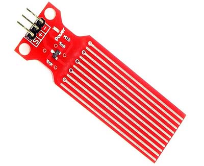
Technical features of the water sensor module (from a seller’s page):
- Operating Voltage: 5VDC
- Working Current: <20mA
- Sensor Output: Analog
- Water Detection Area: 40mm x 16mm
- Mounting Hole Size: 3mm
- Operating Humidity: 10% to 90%
- Working Temperature: -30 to 50°C
- Weight: 3 grams
- Dimensions: 65mm x 20mm
Below you can see the schematic of the water sensor (also sometimes called a rainwater sensor, vapor sensor, or water leakage sensor). As observed, this circuit provides an analog output from circa 0V to 3.6V (dry → wet) when running at regulated 5VDC.
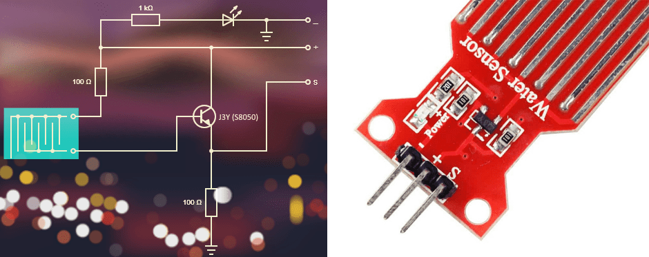
Although I can use a standard voltage comparator IC like the LM393 to convert this analog output to digital (just an on/off output, that’s it), I take a different approach with the 555 timer IC. Next is its schematic!
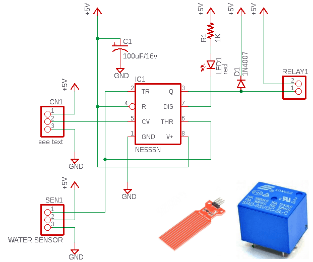
The 555 timer IC is very well suitable for this application as its internal flipflop which controls the output stage is toggled quickly between its two states by internal comparators connected to the two sensing inputs (Pins 2 and 6). When these pins are taken to a voltage above 2/3 of the VCC, the output switches LOW, and then they’re taken below 1/3 of the VCC, and the output swings HIGH.
Timer 555 (IC1) can happily work at 5VDC, and its output (Pin 3) can sink (and source) current enough to handle most low-current relays well. The push-pull output stage of the chip naturally shunts the relay coil when output is HIGH, damping the back-EMF, but it’s probably still good to use the back-EMF damping diode (D1) across the relay coil as well. Capacitor C1 (100uF to 470uF) is employed to absorb potential current transients and noise spikes on the power supply rail.
Before I forget, LED1 is a mere status indicator wired to the “discharge” terminal (Pin 7) of IC1. This LED illuminates when steam falls on the sensor plate (i.e., when the relay is on). Actually, the discharge terminal is an “open-collector” secondary output of 555 timer IC which can sink a fairly large current ideal for driving tiny lamps and electromechanical/solid-state relays.
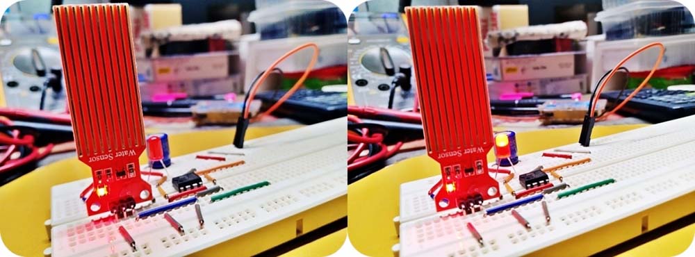
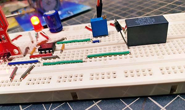
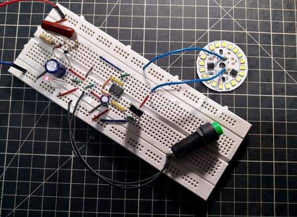
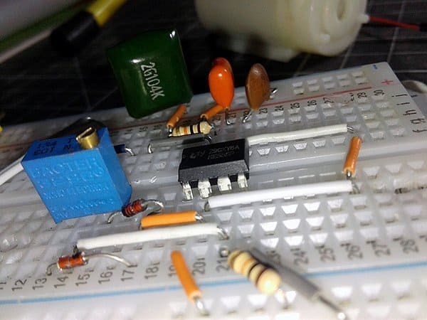
Below you’ll see a partial snap of my quick breadboard setup.
Note that the above circuitry is tailored for use with the water sensor module introduced here. Working with this idea is a bit tricky sometimes as it doesn’t work if the output voltage from the water sensor plate is below the threshold voltage of the relay driver – here it’s around 3.3V. So, you may need to tweak the default threshold through the “control voltage” terminal (Pin 5) of IC1. A potential divider can be used to do this by using the optional 3-pin connector CN1, but remember to set the threshold voltage below the default value. I used a 10KΩ multiturn trimpot to finetune the threshold, but got some good results!
The relay shown in the breadboard shot below is the O/E/N 46-05-2CE (5V/167Ω) PCB relay which’s one of my favorites (https://www.electroschematics.com/toilet-alarm).
Further Thoughts
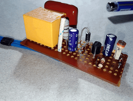
Now it’s time to build your own simple steam sensor. You can either make it on a piece of general-purpose circuit board or on a customized printed circuit board.
With this setup, you can roughly detect the presence (or absence) of steam/vapor (or rainwater) as desired. You can also connect the open-collector output (Pin 7 of IC1) to a microcontroller to monitor the steam sensor status in an application where you want to supervise something in a rather different way. Have fun with it!
For the past few weeks, I have been searching for a dedicated steam sensor and finally found a great one (It has not yet arrived due to some shipping limitations). This is the AHS01IB absolute humidity sensor from Guangzhou Aosong electronics co., LTD (www.aosong.com).
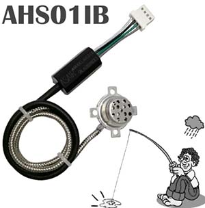
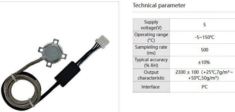
AHS01IB is an ultrahigh response absolute humidity sensor that comes with an I2C interface. It can be used for microwave oven humidity control, dryer humidity detection, steam bath control, air conditioning, moisture control, etc.
Side Note: Absolute Humidity is the measure of water vapor (moisture) in the air, regardless of temperature, and it’s expressed as grams of moisture per cubic meter of air (g/m3). Relative Humidity also measures water vapor but relative to the temperature of the air. It’s expressed as the amount of water vapor in the air as a percentage of the total amount that could be held at its current temperature.
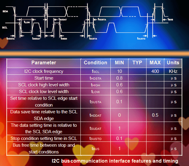
AHS01IB sensor adopts standard I2C communication protocol which’s applicable to a
variety of devices. AHS01IB sensor can be used as an I2C slave device to support the communication rate up to 400kHz bit rate. The I2C address is 0x15, the I2C read instruction is 0x2B, and the I2C write instruction is 0x2A.
Get to know the digital absolute humidity sensor https://www.es.co.th/Schemetic/PDF/AHS01IB.PDF. I’ll probably play with this wonderful digital humidity sensor at some point.
Finally, I hope you liked my simple steam sensor project idea. Give it a Go! Feel free to borrow liberally, and if you spot any issues do let me know.
Can you please share the code for reading the sensor AHS01IB
Same request. If possible, please share the code for reading the sensor AHS01IB
I already replied to this comment but it’s not here. Any technical issues?