As Wikipedia says, a ceramic resonator is an electronic component consisting of a piece of a piezoelectric ceramic material with two or three metal electrodes attached. Like the similar quartz crystal, when connected in an electronic oscillator circuit, resonant mechanical vibrations in the device generate an oscillating signal of a specific frequency (https://en.wikipedia.org/wiki/Ceramic_resonator).
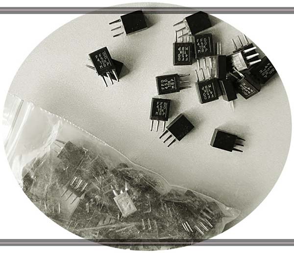
The ceramic resonator is a fairly common part, often used in remote control handsets. If you are not so fortunate to have an old remote control to cannibalize, do not worry, you can still find them in many obsolete landline telephones (see below).
Or you can easily grab a bundle of ceramic resonators (and ceramic filters) from your preferred online retailer. Ceramic resonator for frequency like 455kHz seems to always be in plentiful supply (if you have any interest, it would not hurt to stock up on a few).
Ceramic resonators and quartz crystal resonators work similarly as they both vibrate mechanically when an ac signal is applied to each respectively. The key difference is that a ceramic resonator is made from ceramic components and a quartz crystal resonator from a quartz crystal.
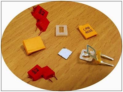
Below you can see the inside of the common and ordinary 455kHz ceramic resonator (https://dalincom.ru/datasheet/CRB455E.pdf). Recall, ceramic resonators often used in television remote controls are available in several frequencies between 375 and 503 kHz.
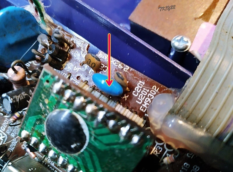
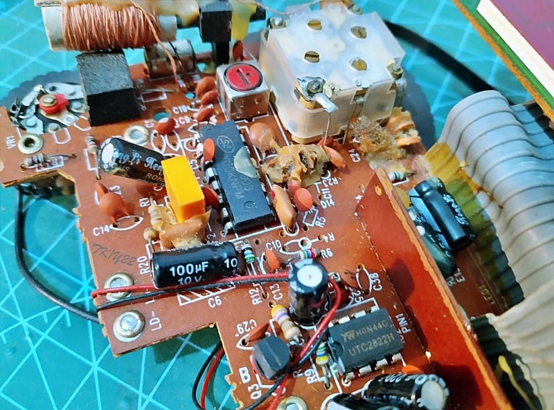
Recently I resumed collecting old radios, remote controls, telephones, etc., because I wanted to use ceramic resonators lifted from such old devices and make something new out of it. The latest in that effort is a defunct AM/FM alarm clock radio donated by my neighbour which also has a couple of ceramic resonators and ceramic filters on its circuit board. It should be noted at this point that ceramic filters are mostly used as bandpass filters while ceramic resonators are mostly employed as oscillators.
OK, now it is time to do a few simple experiments with ceramic resonators that I got from various dumped gadgets and bought from some online stores.
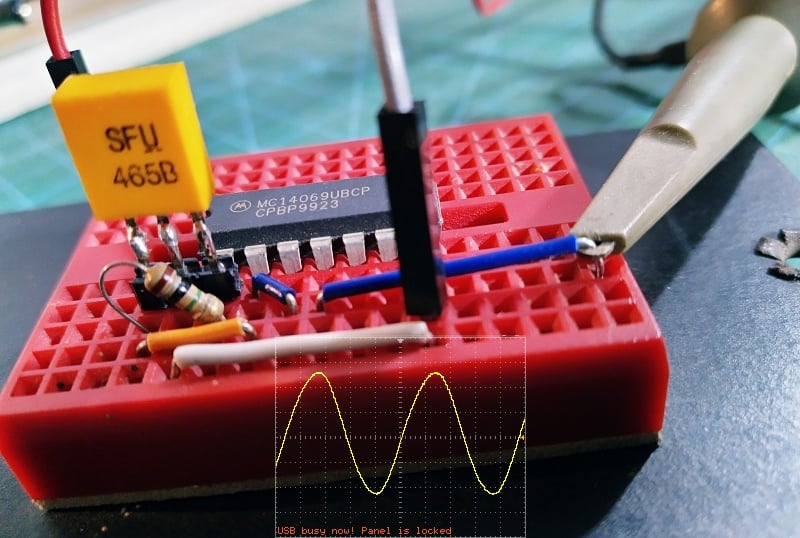
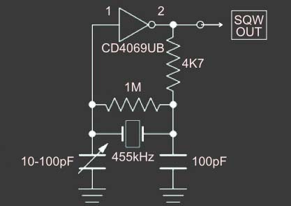
So, the journey continues, what I did the other night was to do some experiments with a canonical ceramic resonator oscillator circuit. The schematic below is one I have drawn after scoping the circuit to check it worked satisfactorily. This barebones version is just a basic oscillator circuit with a CMOS inverter and nothing more!
CD4069UB Datasheet https://www.ti.com/lit/ds/symlink/cd4069ub.pdf
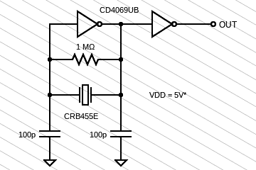
Note that the power supply connections to the CD4069UB IC is not shown. Simply, the positive rail goes to pin 14, and the negative/ground rail goes to pin 7 of the chip. The power supply voltage is not very critical. If you use a standard CMOS version, a supply voltage between 5V and 9V is recommended. But it is crucial, if 74HCU series is used, then the maximum supply voltage is 5V.
As a side note, the oscillating circuits can generally be grouped into three types, that is to say positive feedback, negative resistance, and delay of transfer time or phase. In the case of ceramic resonators, positive feedback is the first choice, and the most commonly used circuit is the Colpitts Oscillator.
So, my real starting point was a basic oscillator circuitry with inverter gates. And, I got a mildly distorted sine wave as anticipated. Then I did some more experiments with the same circuit, but with several ceramic resonators (and some ceramic filters) that I had around. It was definitely a great learning experience.
A slightly improved circuit idea with a variable capacitor (trimmer capacitor) in place of one of the fixed loading capacitors is given below. As you have seen, there is also one damping resistor. This modification provides good frequency stability and allows finer frequency tuning.
Even so, I do not urge you to do your experiments on breadboards as it is a long-familiar fact that breadboards have quite a significant stray capacitance on the order of a couple picofarads between adjacent rows. Likewise, jumper wires and breadboard staplers have a little inductance that becomes quite significant at higher frequencies.
Well, even though this is a far cry from an inspiring narration of my practical experiments, I am glad to be able to share a slice of bread with you. And, there is more to come. I will follow up with a future post about another project that builds on this one!