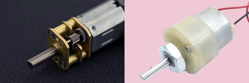
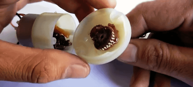
This article explains how to play with the common geared dc motors widely used to drive small robots and simple actuators. Geared dc motor is in fact an ordinary dc motor but with plastic or metal speed reduction gears combined on purpose to scale down its rotation per minute (RPM) rate. In short, geared dc motor ( dc gear motor) is an encapsulated dc motor integrated with a wheelwork consisting of connected set of rotating gears by which force is transmitted or motion or torque is changed by design for some specific purpose!
Know Your DC Gear Motor
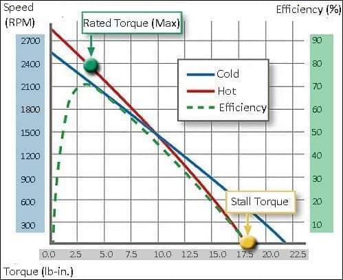
Since the gear motor is a combination of one motor and gears, and the gear head to the motor brings down the speed while increasing the torque output, in order to select the right one you should keep an eye on certain parameters of the motor. The key parameters to be considered here are speed (rpm), torque (lb-in), and efficiency (%). Other most common specs to look at would be voltage, current, and direction of rotation. You should carefully refer the performance curves of your dc gear motor before the final pick. Performance curves of a dc gear motor, usually provided by the manufacturer/seller, lets you know more about the maximum operating efficiency of your motor.
For instance, refer the performance curve of a dc gear motor shown below (thanks to www.islproducts.com). You can see that maximum operating efficiency (70%) of the particular dc gear motor would occur at 3.75 lb-in / 2100 rpm. As torque increases the speed and efficiency decrease, and the increased torque results in poor output performance. The device will eventually fail to function once the motor reaches its stall torque (18 lb-in).
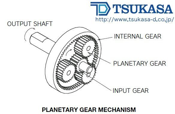
Note that speed reduction by means of a gear mechanism results in increased torque, and the reduction/increase is determined by the gear ratio and efficiency of the gear box. According to Tsukasa Electric (www.tsukasa-d.co.jp), over-all efficiency of the gear motor depends on the number of reduction stages i.e. one average is 90% per stage thus gives 81% for 2-stage, 72.9% for 3-stage, and for a 4-stage reduction it will be 66%. Most compact size gear motors incorporate a “planetary gear” mechanism suitable for limited space applications. Planetary gear mechanism is a heavy-duty type gear mechanism using 3 mating gears (low cost versions comprise plastic or sintered metal) to transmit torque to the output shaft.
On the other hand, heavy-load (self lubricating metal) type gear motors are mainly based on a non-lubricated metal bearing gear mechanism proved good for medium load drive applications and continuous duty cycle operation. In a standard gear mechanism, the gears (other than the output gear) rotate around a shaft that is fixed to the plate.
Now to the specifications of a centre shaft, economic series, dc gear motor, as listed by www.nex-robotics.com
- DC supply: 4 to 12V
- RPM: 200 at 12V
- Total length: 46mm
- Motor diameter: 36mm
- Motor length: 25mm
- Brush type: Precious metal
- Gear head diameter: 37mm
- Gear head length: 21mm
- Output shaft: Centered
- Shaft diameter: 6mm
- Shaft length: 22mm
- Gear assembly: Spur
- Motor weight: 90gms
For more details on motor performance, mechanical structure, and so on, go through www.nex-robotics.com/products/motors-and-accessories/200-rpm-centre-shaft-economy-series-dc-motor.html
How To Drive It?
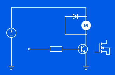
Foolish question, eh? A 12V dc gear motor merely needs 12V dc supply to run, so we can drive it by a suitable 12V dc power supply unit! Admitted, but that’s not enough when you want to drive your dc gear motor through an external electronics circuit or a microcontroller setup. A quick solution then is the use of a proper driver transistor – either a BJT or a MOSFET (with requisite support components) as shown below.
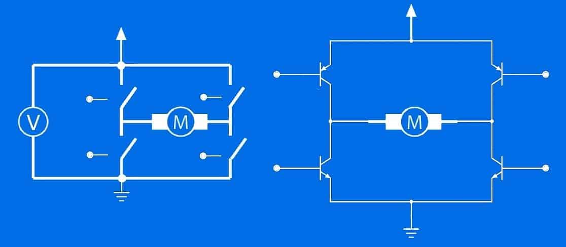
But this simple idea won’t work in certain situations where bidirectional driving of the motor is an absolute necessity. For bidirectional (forward and backward) control of a dc motor you should require one H-Bridge which is a rather simple circuit comprising four switching element (BJT or MOSFET) with a load at its center in an H-like configuration. It’s very easy to build your own H-bridge with just four transistors (integrated solutions also exist) as now a days you can learn how to build H-bridges from many online resources. Here’s a basic representation of an H-bridge:
For those searching for a modular motor driver, the L9110 motor control driver chip from www.asic.net.cn is a cheerful solution. The dual-channel motor driver IC L9110 is widely used in small dc motor drives and stepper motor drives. Tiny modules based on L9110 can be found for 2-4 $ from many web shops, but usually such cheap modules consist two L9110 on board, so we can control two dc motors or one stepper motor with the help of a single module. The L9110 module works with voltages from 2.5V to 12V and can give a continues drive current of 800mA per channel. More than enough for small dc gear motors!
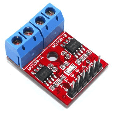 Keep note that unalike many other dc motor driver modules, L9110 module has a single VCC for both control logic and motor driver circuits, and there’s no motor brake function. Since all the four control inputs are tied to VCC through 10K pull-up resistors in the module, the motor outputs are in normally off state. Refer to the table below for pin header connections of the L9110 red module (refer above figure).
| PIN | FUNCTION |
|---|---|
| GND | 0V |
| VCC | 2.5 -12V (5V typical) |
| IB | Input B (Motor-B) |
| IA | Input A (Motor-B) |
| IB | Input A (Motor-A) |
| IA | Input A (Motor-A) |
And, the logical relationship table for one channel:
| IA | IB | MOTOR |
|---|---|---|
| L | L | OFF |
| H | H | OFF |
| H | L | ON/FWD |
| L | H | ON/REV |
Remember that the indicated “Forward” and “Reverse” direction of the connected dc motor actually depends on how it is oriented and wired.
You can learn more about L9110 dual-channel motor driver modules from here – https://www.electroschematics.com/13797/l9110-motor-driver-primer/
Quick Run
First time play of the L9110 module with a dc gear motor may be pretty confusing for a novice. So, to obtain a clear overview I’m using only one channel of the motor driver module for this quick run experiment. The quick run experiment hardware consists of an Arduino Uno board and an N20 type micro dc gear motor.
The Arduino Sketch:
const int IA = 5; // D5 to IA
const int IB = 6; // D6 to IB & GND_Arduino to GND_L9110

byte speed = 255; // Speed Set

void setup() {
pinMode(IA, OUTPUT);
pinMode(IB, OUTPUT);

}
void loop() {
forward();
delay(2000);
backward();
delay(2000);
}

void backward()
{
analogWrite(IA, 0);
analogWrite(IB, speed);

}
void forward()
{
analogWrite(IA, speed);
analogWrite(IB, 0);

}
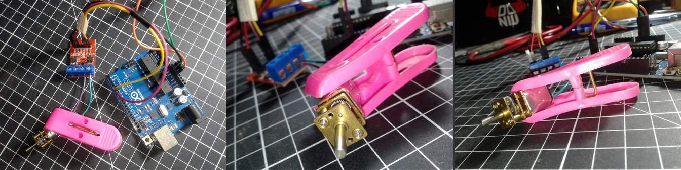
The N20 micro dc gear motor used in my quick run setup is in fact a 12V type with rated RPM of 100. However I decided to use an external 5VDC/1A regulated power supply unit to power the quick run test setup, and it worked well in practice (see the quick run test video).
| ARDUINO UNO | L9110 MODULE | POWER SUPPLY |
|---|---|---|
| 5V | VCC | +5V OUT |
| GND | GND | GND/0V |
| D5 | IA | |
| D6 | IB |
That’s all for now. If you feel the primer here’s fairly useful and maybe elementary, don’t get worry, as there’s plenty of stories to come. In a future article I’ll look in detail at multiple drive modes – including variable speed and two-way direction!