Audio signal injector is a must to have little tool for troubleshooting audio circuits. Connecting the audio signal injector to the circuit under test you should be able to hear its tone in the speaker of the audio device so that beginning at one end of the circuit you can walk your way around the circuit, following its schematic to find where the tone is lost. Here’s one circuit of a compact audio signal injector for those who don’t have a rack full of luxurious test equipments. As pointed above, it can be used for working on an audio circuit that requires some kind of hearable signal for testing various segments of the circuit.
Circuit Diagram & Description
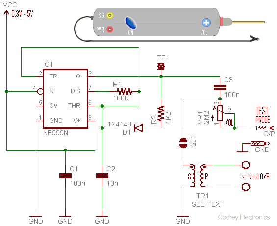
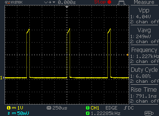
With a bit of Googling you can find numerous signal tracer circuits on the net and although I built many of them, the circuit presented here is centered on the venerable tiny timer chip NE555N (IC1) because of certain good reasons. As can seen in the above circuit diagram, IC1 works as a free running oscillator that gives about 1.2KHz audio tone at about 4v p-p. Shown below is an oscillogram taken while I was testing my initial prototype wired on a MB-102 breadboard powered by regulated 5v dc supply (Scope probed to TP1).
R2 (1K2) and C2 (10n) are the key components in the circuit responsible for shaping the frequency of the output audio tone. However there’s an extra 1N4148 diode (D1) in their path, inserted deliberately to ‘sharpen’ the audio tone. Further, you can see a 100nF dc blocking capacitor (C3) and a 2M2 volume restrainer trimpot (VR1) there in the circuit diagram. The dc blocking capacitor offers protection against dc voltages coming back from the circuit points under test. The trimpot is optional, so you may replace it with a fixed value resistor, 10K for instance.
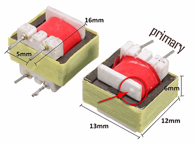
In a few situations you may like to get perfectly isolated output signals from the audio signal injector. If so you can add a common 1300Ω:8Ω audio output transformer at the output of the circuit as marked in the circuit diagram. Take note that the audio output transformer (TR1) is reversely wired here i.e. in 8Ω:1300Ω (S:P) way because I observed a meek and right tone output in that ‘absurd’ configuration. Anyway you’re free to ‘reverse’ it to start your own peculiar experimentations (I don’t care). See, the solder jumper (SJ1) lets you enable/disable the isolated signal output option. Generally, similar audio output transformers are still used in many audio power amplifiers to transform the high-voltage, high-impedance output of their transistor-based signal driver circuits to the low-voltage, low-impedance output demanded by standard loudspeakers. The 1300Ω:8Ω value clearly denotes the typical impedance ratio (P:S) of the transformer.
Construction & First Test
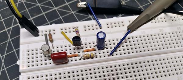
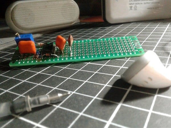
The whole circuit can be assembled on a small piece of rectangular perfboard (see the start of my construction). Components are somewhat crucial but the device can probably be made from junk box parts.
Although the circuit will work happily from a 3.3 to 5 volt dc supply, the latter is commended and thus you can add a low-current 5 volt regulator circuitry on board to run the device from one internal/external 6F22 9V general purpose battery or the like. Disconnecting the power supply can be achieved using a slide switch in the positive line starting from the battery/power supply source.
Now you just need to find a suitable plastic case and mount all the parts into it. A common glue pen or marker pen will be a good pick for the enclosure. The probe tip can be made from a salvaged multimeter test lead but even an old nail, a pointed machine screw, or an injection needle would do the job just as well. The ground cable (may be another multimeter test lead) should have a small black alligator clip at its loose end as it makes a comfy test clip lead for rigid ground connection.
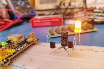
To quick test the finished model, connect your audio signal tracer’s test probe tip to the signal input point of an audio amplifier, and the clip lead to its ground rail. The audible test tone should come out of the loudspeaker linked with the amplifier, at least when everything is working all right!
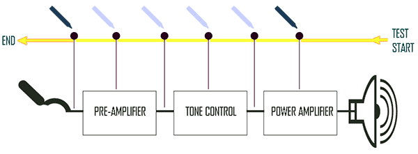
Virtually any maker can make this simplest audio signal injector to assist in signal tracing efforts of audio devices, audio portions of ham radio rigs, etc. Suppose you’re repairing an audio amplifier system. If you have success at injecting the test tone at a final circuit point, then move back to adjacent point, and so on, until you have probed the point in the circuit where the tone perceptibly disappears (or drops) significantly in level (see next reference graphics). This says you that the trouble rests somewhere between the last successful circuit point and the most later circuit point at which you failed to hear the injected tone. In this way most problems can be traced very easily.
As always, I’m happy to offer advice on stuff I’ve written, and indeed take advice. So, feel free to share your thoughts here!