Steady Hand Game, also known as Buzz Wire Loop Game is a tabletop game which involves guiding a metal ring (the wand) along a serpentine length of bare wire (the loop) without touching the wand to the loop. The wand and loop are wired to a sensor circuit in such a way that, if they touch, the system raises a visual and/or audio alert. Seems simple however Steady Hand/Buzz Wire Loop Game is in fact a challenging game so the player has to get the right balance between speed and skill in order to obtain a successful score!
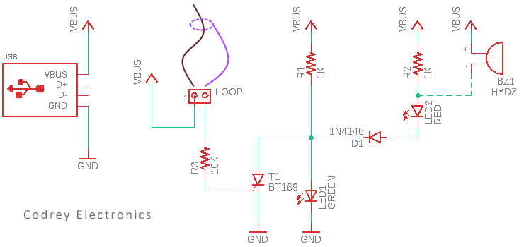
In this post we will build our own version of the classic game for steady hands using a bunch of commonly available inexpensive electronics components. Well, let us start with its circuit diagram.
Here is the list of key parts required to build the USB-powered Steady Hand Game:
- BT169D Thyristor x1
- 1N4148 Diode x1
- 5mm Diffused Red LED x1
- 5mm Diffused Pure Green LED x1
- 1KΩ ¼ W Resistor x2
- 10KΩ ¼ W Resistor x1
- 5V Active Buzzer (optional) x1
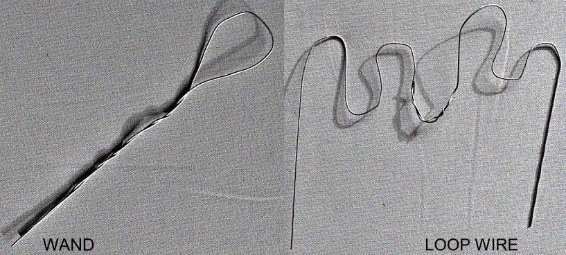
There are lots of different ways that you can construct the wand and loop wire for this game project but a very simple and effective way is to make it from two pieces of moderately stiff uninsulated wire.
To do that, first twist a short length of bare wire into a loop with a handle. Next, take a long piece of exposed wire and bend it into a wiggly shape to form the loop wire.
At last, link the wand and loop to the input connector (LOOP) of the circuit using a pair of suited flying leads.
The below swept up illustration will give you a more percipient idea of how to shape up it. Anyway, I am not going to discuss about the final enclosure (case) construction ideas here, I would like to leave it as an exercise for you (anyway remember to always aim for a superior quality finish).
As can be seen in the circuit diagram demoed before, it is a pretty simple thyristor-latch setup powered by a regulated 5VDC (USB) power source. Working of the circuit is easier to understand and as follows.
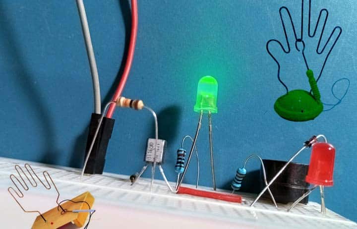
Initially in the standby state, the green indicator (LED1) lights up to indicate that the Steady Hand Game is ready for use.
The object of the game is to carefully move the wand along the zigzag loop wire without touching it (the goal is to be fast and at the same time to be efficient, having the least number of touches).
When the wand touches the loop, the green indicator turns off instantly and the red indicator (LED2) wakes up and stays on to announce the foul. If the optional active buzzer (BZ1) is there, the player will also hear a faint buzz at that time.
Thereafter, a power cycling is mandatory to restart the game i.e. once it is triggered it remains on (latched) to prevent cheating until the power is removed or it is reset.
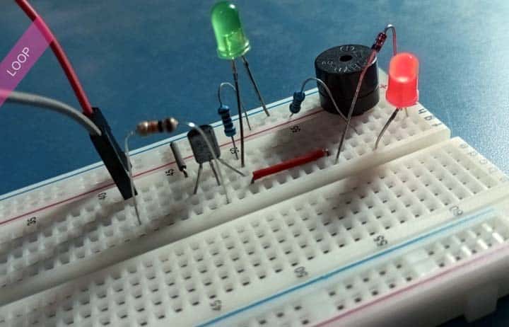
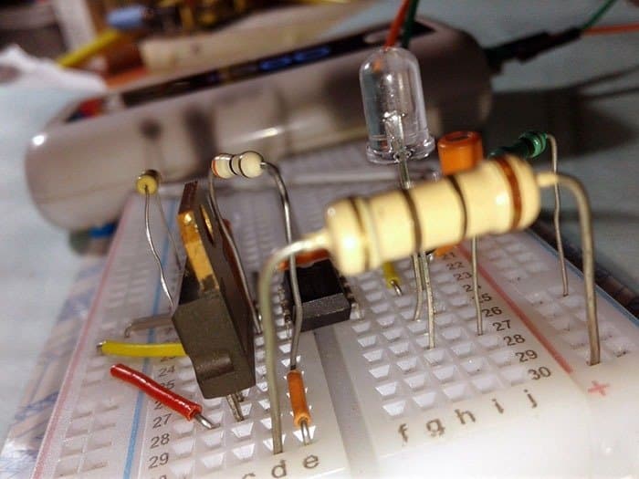
To make sure everything works as expected, I configured a quick test setup on a regular breadboard. Then powered it up with a cheap USB power bank and it worked without any issues.
As you may have guessed, the active buzzer here is getting very low operating voltage which is technically incompatible. But it works happily and makes a weak output, hopefully plenty for a silly portable gaming device like this.
As a side note, the BT169D is a sensitive-gate thyristor. Therefore, it is advisable to add an appropriate pulldown resistor between its gate lead (G) and cathode lead (K) to avoid false triggers that may occur in certain noisy environments.
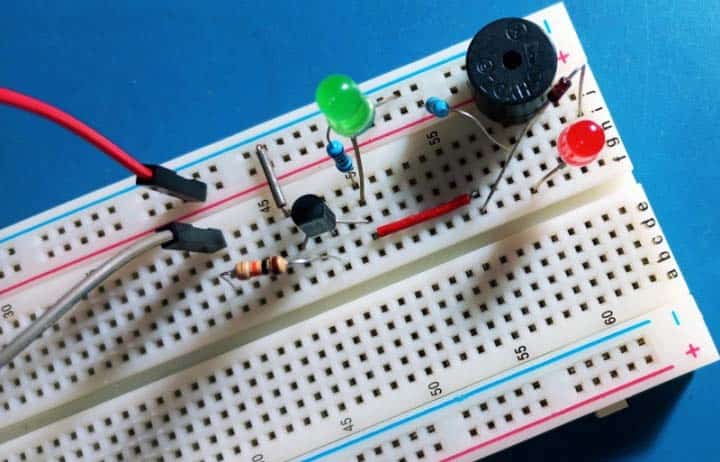
Here are the approximate voltage levels associated with the various circuit components in my breadboarded prototype for your quick reference (VBUS = 4.99VDC):
- VF (Green LED): 3.10V
- VF (Red LED): 1.85V
- VF (1N4148): 0.60V (on-state)
- VT (BT169): 0.80V (on-state)
- VBZ (Buzzer): 1.65 (on-state)
Well, that is all for today…
Now try this! But just because I showed an easy mod version of a steady hand game circuit with a common thyristor switch does not necessarily mean that a buzz wire game can only be designed and build that way. So, do not hesitate to adapt and experiment. If you are stuck and need some help, drop your related comments below.
If you are doing your own search, most of the time you will likely find countless circuit ideas which look alike but might have a few variations. Nevertheless, always be cautious as anyone can put anything on the internet, even if it has serious flaws. Good Luck!