Inspired by some commercial automotive side marker lights, I recently built a general purpose 3-LED flashing marker light. It can be used as an attention light in and around your home, especially at night.
So, here are the design details of that little marker light designed to run safely from multiple power sources like a 5V/9V wall wart or 9V battery.
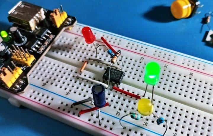
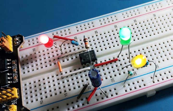
Actually, this is a 555 timer IC based 3-LED flashing light as you can see in the schematic below. It uses a 5VDC power supply to drive three different colored LEDs, red, green, and yellow, but you can certainly tweak the circuit to suit your personal taste and needs.
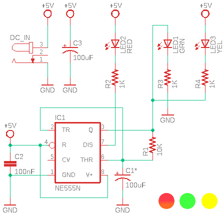
Somewhat strange, this scheme uses two pins of the NE555 chip (IC1) to drive three LEDs (LED1-LED2-LED3). That is, its output pin (Pin 3) is wired as usual, and the discharge pin (Pin 7) is wired in a slightly unusual way.
The Pin 3 output of the 555 chip comes from a high-current totem-pole stage, and is capable of sourcing or sinking up to 200mA. The output uses a push-pull architecture and can drive from 0V to approximately 1.7V less than Vcc (CMOS version can drive output up to Vcc rail)
The Pin 7 is the open-collector of an internal NPN transistor, the emitter of which goes to GND. The conduction state of this transistor is identical in timing to that of the Pin 3 output stage, that is, the transistor acts as a switch which is in phase with output.
As you might already noticed, this is a pretty simple free-running (astable) oscillator circuit that routes Pin 3 of the timer chip (IC1) directly to the timing capacitor (C1) wired to Pins 6 and 2 of the timer IC via a single resistor (R1).
So, when the output at Pin 3 is HIGH, the capacitor C1 charges up through the resistor R1, and when the voltage across the capacitor reaches 2/3Vcc, Pin 6 causes the output at Pin 3 to change state and goes LOW.
Then the capacitor C1 discharges back through the same resistor R1 until pin 2 reaches 1/3Vcc causing the output to change state once again. The capacitor C1 continually charges and discharges between 2/3Vcc and 1/3Vcc back and forth through the same resistor creating an eternal HIGH and LOW state at the output Pin 3.
Since the timing capacitor charges and discharges through the same resistor, the duty cycle of this basic setup is very close to 50%. The series of square wave output pulses generated have a frequency (f) equal to approximately 0.7/R1C1.
As an aside, keep note at this point that this is not an accurate method of producing a 50% duty cycle output using a 555 timer chip, either Bipolar or CMOS type. The circuit can bring out a duty cycle that is close to 50% (1:1) but when a load is added to the output of the timer chip, the voltage drops across its internal output transistors will increase and the duty cycle will shift!
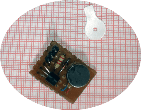
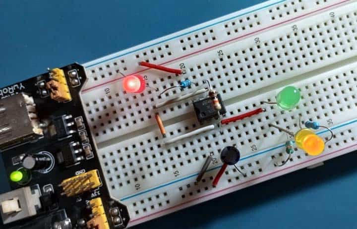
The entire circuit can easily be built on a small stripboard, and if you are skilled enough at soldering, you can even try the point-to-point construction method. The value of capacitor C1 can be changed to alter the blink speed, but sticking to the 100uF value shown will not cause any troubles. Anyway, the best values in this case are 22uF, 47uF, 68uF and 100uF.
As a glass of my usual, I built a quick and dirty breadboard version for my first round of evaluations, and it did work flawlessly.
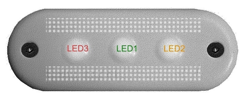
For the case, a 3D-printed translucent one is preferred, but you can try any of the disposed vehicle side marker light casings for a budget touch of luxury. The orientation of the LEDs is not very critical, but a favourable layout pattern (R-G-Y) is loosely indicated below.
Later I may transform this simplistic design to an SMD version for total compactness. Luckily, I have all the necessary chip parts on hand, but need to design a nifty PCB for it. I will get to it one day.
Have fun, that is what it is all about!