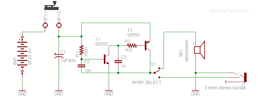
I have received numerous requests for a simple, cheap and entry-level ham radio world project and the result is this do-it-yourself Morse Code Practice Oscillator usually called simply as Code Practice Oscillator (CPO). This project is very helpful for amateur radio (Ham Radio) enthusiasts to practice the sending and receiving of Morse Code. The schematic diagram of the constructional project is as shown below.
Schematic Diagram
Parts List
Parts list of the project is shown below:
| Label | Description |
|---|---|
| T1 | S8050 NPN Transistor |
| T2 | S8550 PNP Transistor |
| R1 | 100K ¼ w Resistor |
| R2 | 1K2 ¼ w Resistor |
| C1 | 1uF/63v Electrolytic Capacitor |
| C2 | 10n (0.01uF) Ceramic Capacitor |
| C3 | 1n (0.001uF) Ceramic Capacitor |
| SP1 | 8Ω/500mW Loudspeaker |
| S1 | SPDT (single pole double throw) Slide Switch |
| J1 | 3.5mm Stereo Headphone/Earphone Socket |
| BAT | 6F22 9V General Purpose Battery |
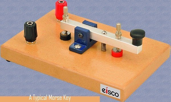
| KEY | Morse Key |
Design Description
The design is in fact a clever adaptation of the traditional transistor-based tone generator circuit. However, the circuit introduced here uses cheap components available everywhere. In the circuit, the 10nF capacitor (C2) works as the key timing component to make the frequency of the tone. The 100K resistor (R1) limits the base current of the NPN transistor S8050 (T1) and supplies current to charge C2 and thus forms a part of the frequency determining RC network. The 1K2 resistor (R2) sets the current through the collector-emitter (C-E) junction of T1, and the base-emitter (B-E) junction of T2. Note that basically the NPN-PNP transistor combination creates a high-gain DC amplifier, where the second PNP transistor S8550 (T2) drives a small 8-Ohm (8Ω) loudspeaker (LS1).
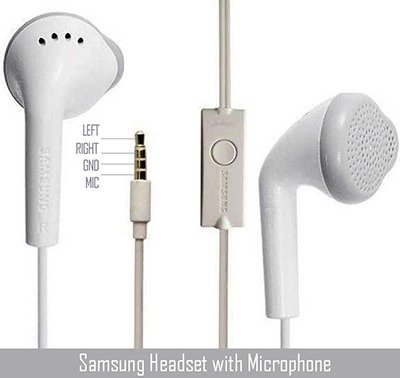
Furthermore, the output selector slide switch (S1) allows you route the tone signal output either to the built-in loudspeaker (SP1) or to the 3.5mm standard stereo headphone/earphone socket (J1). You can plug almost all mobile phone stereo headsets (see next figure) into the CPO through J1 as the socket is wired in a special manner to drive left (L) and right (R) channels of the connected headset simultaneously. In other words, a common mobile phone stereo headset (32Ω x2) here works as a monophonic headset (64Ω) but with a two-fold earpiece!
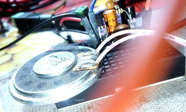
CPO Construction
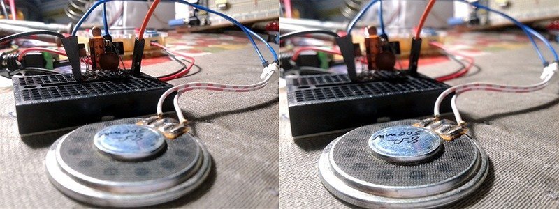
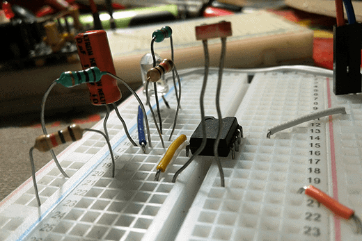
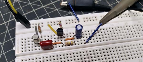
Although I made my quick prototype on a small breadboard (see next figure), I’d like to advise you to build the entire electronics on a flake of common veroboard. If the circuit doesn’t work, you should go over the assembly again, making sure you’ve not left anything off the circuit board. After successful construction and initial tests put the final circuit board (preferably with the loudspeaker and battery) in a small soapbox. Make sure the key terminal, slide switch, and the audio socket have been fitted right in the enclosure.
Finally…
Congratulations, you’re right on your way to learning and practicing Morse code! Morse code, named for Samuel F.B. Morse, is one of the first methods of quickly communicating over broad stretches of land, sea, and air. Morse code is still widely used across the globe by amateur radio enthusiasts (HAMS) and by professionals in certain fields. The code practice oscillator presented here would be great for anyone looking for science fair-like project ideas, too.
Back into the design, you can fiddle with the original design to create your own code practice oscillators. By placing a different value for R1 (and/or C2) you’ll be able to hear an output tone with a different frequency (default ~ 1.6KHz). Likewise, you can see one ‘unorthodox’ capacitor (C3) in the schematic. It’s included intentionally and its effect will be quite noticeable – you can of course remove/change it just to find out the role of that little capacitor in this particular code practice oscillator circuit.
How it works?
Following is an elementary explanation about the working principle of the tone generator/oscillator circuit. At first, presume that base of T1 gets enough voltage (600mV) and it starts to turn on. As T1 is directly coupled to T2, if T1 turns on, T2 also turns on and naturally initiates current flow through SP1. This time both ends of C2 start to rise, and turn on both transistors hardly until they’re fully turned on. Now C2 begins to charge through the base-emitter junction of T1 and the collector-emitter junction of T2. When C2 becomes nearly charged, the charging current reduces and T1 gets down to turn off slightly. This forces to turn off T2 too, and the voltage on the collector of T2 falls. Next, both ends of C2 start to fall and finally turn off both transistors. This ceases the current flow through SP1. Thereafter, C2 starts to charge again via R1 but in the reverse direction so that the voltage on the base of T1 rises to 600mV. At this point T1 turns on again (with T2) and the cycle repeats. Get it?
Useful Web Links

Do you have a parts kit for sale?
Bill Pierce
Sorry, I do not sell parts/do-it-yourself kits – it sounds like a great business, though. BTW, Thank you so much for your keen interest in my little project.
Your use of the word “hardly” is incorrect because it means “something done in the slightest”; like, for example; “I used hardly (very small amount) any effort to lift the weight.”
You can turn a transistor on ‘hard’ (full on), but if you have it ‘hardly’ turned on it means that you have it ‘only just’ (slightly) turned on.
Allan: I usually don’t find time to reply to such ridiculous comments as I don’t even have enough spare time to do other worthy things. But your question deserves an answer.
The statement “hardly” is used here in a very broad sense. You should read that line again: “This time both ends of C2 start to rise, and turn on both transistors HARDLY UNTIL THEY’RE FULLY TURNED ON….”
Missed your morning coffee?
Further, connect an oscilloscope (if you have one) to the relevant circuit points to see how it “slowly and with difficulty” goes to a fairly fully turned on state. Hope you have the knowledge and skill to understand this!