Aim of this article is to provide a simple circuit to drive EL (Electro Luminescent) components. The minuscule driver design you can find here will render decent power to lights up a few feet of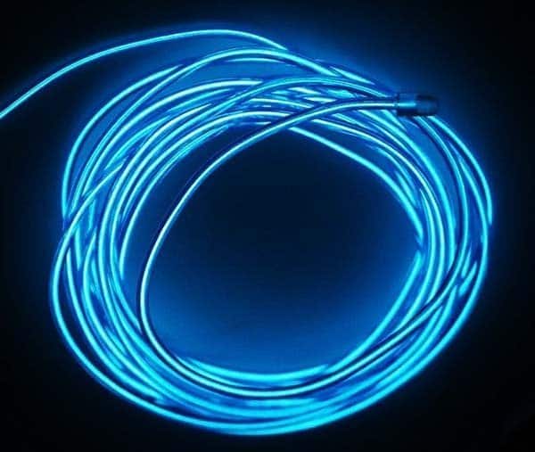 common EL Wire.
EL Wire
Electroluminescent (EL ) Wire, also called Flexible Neon Wire, emits light along its entire length but without any heat radiation. Wrapped by colorful plastic tube on its surface, it appears similar to common wire but is a very robust material. EL Wire can withstand fairly extreme temperatures between -20°C and 50°C, and the robust wire itself is water resistant.
EL Wire Driver/Inverter
An AC source is essential to power EL wire and it must be a sine wave with zero DC component. A simple EL Wire inverter can drive up to 1-3 meters of classic EL Wire. The AC output voltage of such an inverter should be between 50V-120VRMS, and its frequency is in 60Hz to 2KHz range. Most EL Wire inverters, however, run at around 100VAC and 2KHz (+/- 10%). Note that higher voltages (and higher frequency) result in a brighter display but reduce the overall wire life.
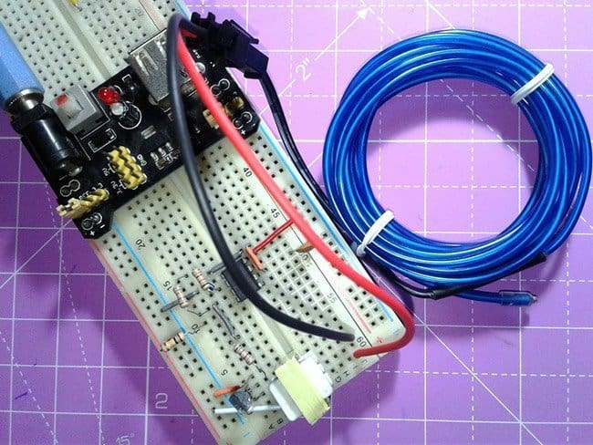
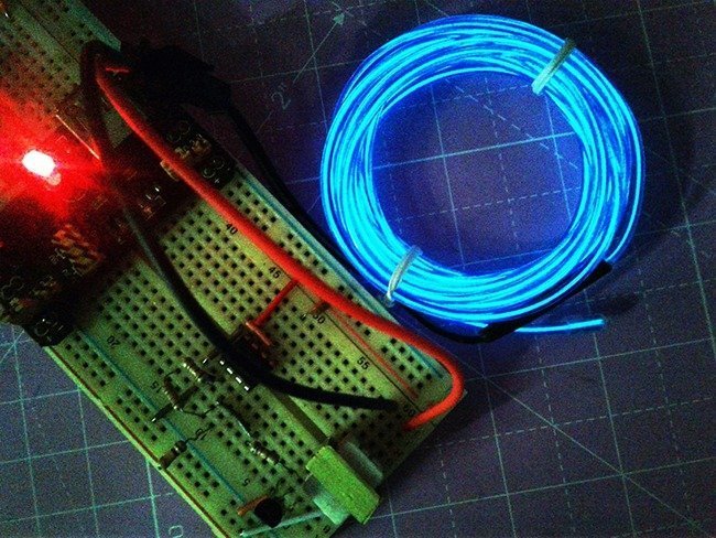
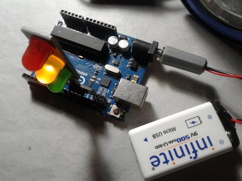
Following is the tried and tested circuit diagram of the little EL Wire driver/inverter. It employs commonly available inexpensive components and would work fine on a couple of batteries. Anyway, first of all note that It’s not much powerful so don’t expect it to light up a long EL Wire/Tape. It cheerfully works for smaller wires and such. Prototype was successfully tested with the common 1 meter (& 3 meter) blue EL-Wire sold by Amazon, Flipkart, Banggood, etc.
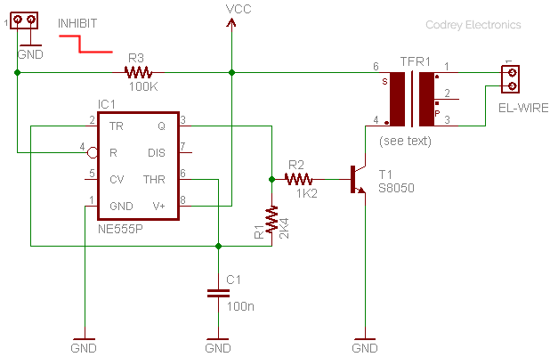
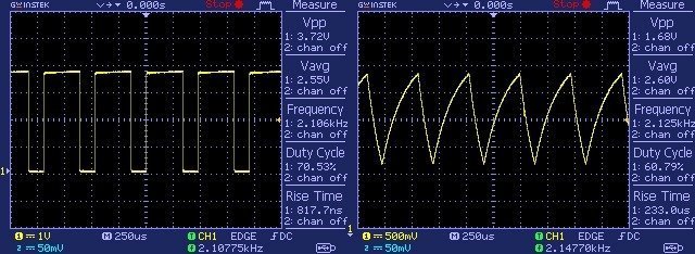
The circuit built around NE555P (IC1) is configured as a “tricky” astable multivibrator (AMV) to give an output close to 2KHz. The output is used to drive a reverse-wired common miniature audio output transformer (1300:8) through a S8050 transistor (T1). Isolated (Zero-DC) output winding of the transformer (TFR1) can be connected to the EL-Wire preferably through a standard JST connector/cable. RC components R1 & C1 here sets the astable frequency. There’s also a “INHIBIT” input to disable the oscillator by an external circuitry (low-to-disable). Oscillograms taken while oscilloscope was probed to pin 3 (left) and pin 2 (right) of IC1 in the breadboard prototype (5Vdc) is given below.
EL Wire Preparation
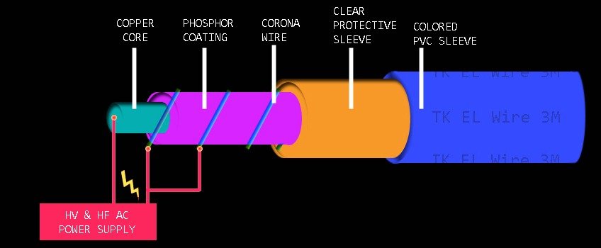
EL Wire looks like this on the inside (see next figure). You must attach one lead of a twin-wire power cable to the neon wire (copper core wire) and another to the corona wires (very thin copper wires) to make it glow. Since EL Wire will be getting AC from the driver, the two power input wires don’t have any polarity but the most important thing to ensure is that there’s no short circuit between them. Further, always make sure to terminate the free (unconnected) end of EL Wire rigidly.
Here you can find a step by step instructions that will teach you how to handle your EL Wire http://www.elwirebestbuy.com/do-it-yourself-el-wire/
A few hints for getting the most out of the build
This flexible circuit can be used to power high impedance, high voltage, low current devices such as EL-Wire lamps and small fluorescent tubes. The S8050 driver transistor did not even require a heat sink with this design, and the given circuit parameters accept up to 9-12V dc input (frequency might change accordingly). Best of all, this design is easy and fun to build, using readily available components. Anyway it’s a good idea to use bypass capacitors as the circuit can be very noisy. Besides, try to experiment with the value of the 1K2 resistor to get a good tradeoff between EL-Wire brightness and battery drain, that means, the base current and drive frequency must be fine-tuned to make the overall current consumption moderate, while maintaining optimum brightness on the EL-Wire. Although most small transformers might work in this “tickle stick” inverter-type design, the mentioned audio output transformer is highly recommended because of its small size and ease of use. Finally, do not touch the output wires of the transformer. You have been cautioned!
I bought all key components from Banggood:
Hey, I just found your circuit but upon inspecting the schematic I saw, that you didn’t connect the “DIS”-Pin to the capacitor node somehow. So there will be no switching signal present on the output.
Also the capacitor never gets charged up, as it additionally isn’t connected to the voltage supply 🤔
Regards,
Hannes
Hannes: It seems you haven’t delved into the distinct design concepts of the 555 timer IC. The schematic is 100% correct and no further amendments are required.
Note that it’s okay to connect pin 3 of 555 directly to the timing capacitor C1 via a single resistor R1 as implemented here. Then, when the output at pin 3 is High, C1 charges up through R1, and when the voltage across C1 reaches 2/3Vcc, pin 6 causes the output at pin 3 to change state and goes Low…
The output waveform frequency is equal to: 0.722/R1C1
This is just a quick explanation as there is not much time now to explain the math in depth (perhaps another day). Thanks!
.
Are there any sources you’d recommend for scaling up to larger lengths of EL? Trying to build a larger project and really want to craft the whole thing from scratch.
Kevin: I don’t have a ready-to-go solution for you yet, but here are some significant points that might be useful:
First, for optimum efficiency, the EL Wire inverter needs to be appropriate for the resistance and capacitance EL Wire characteristics, both of which are determined by the fiber length.
Next, inverters designed to light up EL Wires ranging from several inches to several feet of wire are available today. Their typical DC input voltage ranges from 1.5V dc to 12V dc (12V+ for 50+ft drive), and the operating frequency is usually in 1.5 kHz to 3 kHz range.
Finally, you can use a dedicated EL Panel driver IC from the HV850 series to build your own EL Wire controller.
As an example, the Supertex HV850 is a high voltage driver designed to drive EL lamps of up to 1.5in2, with capacitive values up to 5.0nF. The HV850 converts a low voltage DC input to a high voltage AC output across the EL lamp. Search Google for more.
Thanks!