In this post, I will attempt to share the design idea of a doorbell sensor that can be build using just a handful of inexpensive and easily available electronics components. When cleverly integrated into your home automation IoT project, you can use it as a way to receive phone notifications and trigger other actions when your doorbell rings.
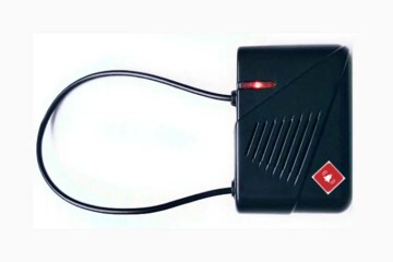
First of all, note that my preference is to set up the notification system while keeping the existing door bell and doorbell button intact. Also, there are many roll-your-own design sparks out there, but I prefer to use a dedicated adapter designed specifically for this task rather than repurposing a commercial device that is not intended to handle standard AC230V doorbell potential.
Okay now let us see its schematic drawing given below.
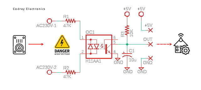
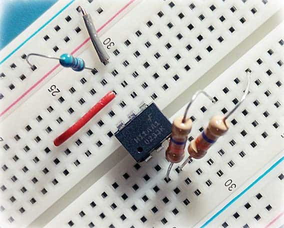
This minimalistic design is centered around a single component, the bi-directional input optically coupled isolator H11AA1.
The HA11AA1 features two inverse parallel gallium arsenide infrared LEDs coupled to a silicon NPN phototransistor in a 6-pin industry standard DIP package. It has a minimum CTR of 20 %, a CTR symmetry of 1:3 and is designed for applications requiring detection or monitoring of AC signals.
As a side note, CTR (current transfer ratio) of an optocoupler is a parametric quantity similar to the DC current amplification ratio of a transistor (hFE). It is expressed as a percentage indicating the ratio of the output current (IC) to the input current (IF).
Simply put, CTR(%) = (IC/IF) x 100. However, keep in mind that CTR is not a static value as it is affected by aging, the forward current, the collector-emitter voltage, and the ambient temperature.
This doorbell sensor is designed to be wired in parallel with the existing doorbell so when the doorbell operates, AC supply reaches at the input of the doorbell sensor passes through 47KΩ ½ W resistors R1 and R2 and drives the antiparallel LEDs inside the bidirectional input optocoupler H11AA1 (OC1). This makes the output of the optocoupler’s internal LEDs high enough so that it will excite the internal phototransistor to deliver a sensible signal at its collector terminal. Note, the input current, close to 2.5mA at AC230V, is set marginally low on purpose to minimize the potential degradation in CTR over time, which is usual with optocouplers.
The output side of the optocoupler is galvanically isolated from mains electricity. So, there you can safely connect the GPIO of the microcontroller in your home automation project. The 10KΩ resistor (R3) works as a 5V pullup resistor.
So, when the AC input voltage is zero, the output will be High, in this case, 5V. However, you must be aware that there is no “clean” signal at the output when the AC input is 230V (see below oscillogram).
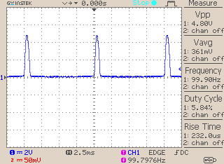
To make it a little smoother, a 10uF electrolytic capacitor (C1) is added at the output, between the collector and emitter terminals of the optocoupler. This time the output signal looks like this:
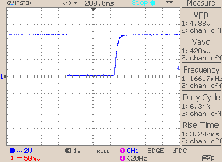
In the oscillogram above, I showed the instant of pushing (and releasing) the doorbell button. As you can see, there is a reasonably smooth transition at the output.
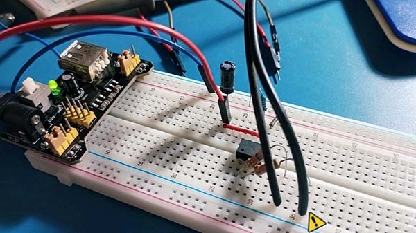
So, you have now learned how to easily build your own poor man’s doorbell sensor IoT module/adapter, but without using any expensive components or following someone’s exotic circuit ideas. Just a pretty cheap bidirectional optocoupler, three resistors, and a capacitor did the trick.
Jumping to an interim conclusion, it amazes me that most smart home automation project makers forget about the doorbell at the front of your home. At the very least, I want you to get a smartphone alert if someone rings your doorbell. That way you can quickly see the front door peephole security camera or turn on your porch/gate light, right?
For intrepid home automation enthusiasts, you can also try building your own IoT doorbell. Even so, you might find this crude IoT doorbell sensor/adapter idea useful in that regard as well. Be future ready!