Pretty little 4V Sealed Lead Acid (SLA) or Sealed Maintenance Free (SMF) batteries are widely used in portable electronic gadgets such as mosquito bats, kitchen scales, healthcare instruments, etc. The most common 4V SLA rechargeable batteries have capacities from 500mAh to 1Ah, but compact types up to 4.5Ah are readily available today.
Oh, and this is another post fairly related to this topic, published here a while ago 12V SLA Battery Charger Guide
This post is just a recap of my thoughts on charging them safely. You can literally see hundreds of simple-to-complex charging ideas all over the web, but stay with me for a few seconds and think a little more.
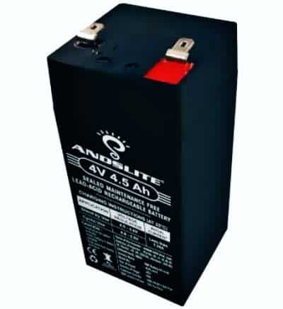
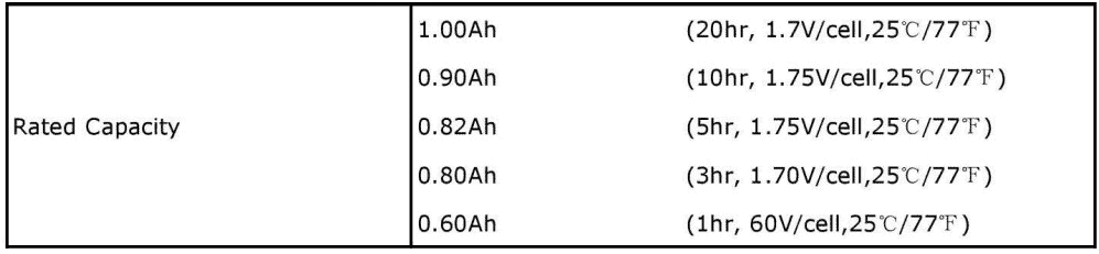
So, let us take a quite common 4V/1Ah (20HR) “standby series” valve regulated sealed lead acid battery at this time.
Note that a standby/floating battery is designed to be used on mains powered electric charge for its entire life and used only in an emergency. You can see it in emergency lights, electric doors, etc. On the other hand, a “cyclic” battery is designed to be heavily discharged or laid on a less constant form of charge, for example, solar or wind power system. (https://valen.com.au/whats-the-difference-between-standby-and-cyclic-batteries/).
Nominal voltage of the abovementioned battery is 4V, and its nominal capacity (20hr) is 1Ah. Also, it has an internal resistance close to 50mΩ. Internal resistance of a cell is the opposition offered to current within the cell introduced by the resistance of the plates, the active material, and mainly by the electrolyte.
See this whitepaper https://actec.dk/media/documents/68F4B35DD5C5.pdf
In standby use, the charge current of the 4V/1Ah SLA battery should be less than 0.25CA at nominal operating temperature (25C°), while the charging voltage should be within the exhorted range of 4.5V-4.6VDC.
It is probably worth noting that since the 4V/1Ah standby battery is rarely cycled, but kept constantly on charge, it can be very long lived if charged at the float voltage of 4.5V to 4.6V (at 25°C). This safe charging voltage prevents the battery from losing water during long float charging.
Oh, I am sad, I neglected to mention that the capacity is usually stated assuming that the battery will be discharged over a 20hr period (see below).
Of course, there are many pieces to the puzzle, but charging a 4V/1Ah SLA battery is not a difficult task. I will wrap up this little post with the circuit of an elemental 4V/1Ah SLA battery charger.
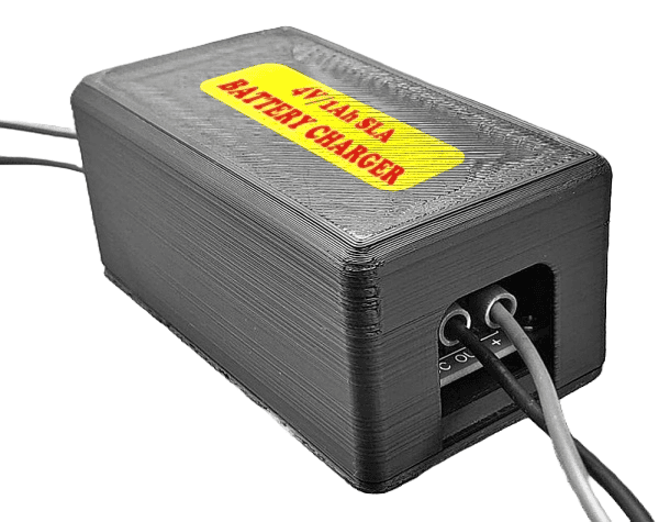
TL; DR: I recently faced the necessity to get an adaptable 4V/1Ah SLA battery charger module and then a meek design spark came to the rescue. So, I finally arrived at the schematic shown below.
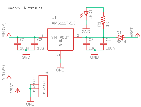
For some reason the charger is designed as a bolt-on module, centered around the ubiquitous AMS1117-5.0, a low-drop linear 5VDC regulator.
It also has a Schottky barrier rectifier SS14 at its output to prevent reverse flow from the battery when there is no input voltage (VIN).
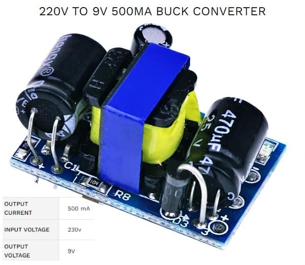
An external 9V/500mA SMPS module (see below) is the only additional requisite to fulfil the battery charging system.
In my humble opinion the scheme proposed here has no real advantages over normal web circuits. Also, there are no smart security features or protection systems. The only imaginable advantage of this constant voltage battery charging method is that one can safely charge the battery as desired. Nevertheless should you ever need another feature-rich design solution, let us have a discussion.
Since an LDO voltage regulator is used for supplying charging voltage to the battery, a soft start would be desirable. The change necessary for getting a smooth startup feature would be extremely simple – use an appropriate NTC power thermistor between the power source and the battery.
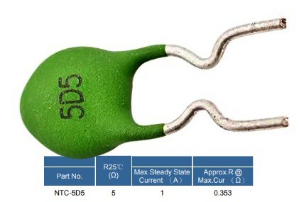
An NTC thermistor limits the initial current flow with its high initial resistance, and then its temperature rises because of energization and its resistance falls to a few percent of its level at room temperature, thus achieving a power loss that is lower than when a fixed resistor is used. My test was carried out with a randomly picked 5D-5 NTC power thermistor (see below).
In place of a conclusion, I would not claim a patent for a primitive design like this (ha ha). By this post I simply want to share a useful design pattern with you, my beloved readers. That is all for now. See you then!