Recently I have received a few messages from a follower who is interested in making a simple relay box that will help him operate some regular electrical devices using the control signal from a common microcontroller like Arduino. So, without further ado, I designed a poor man’s smart plug to meet his needs.
Poor man’s Smart Plug is in fact a portable AC230V outlet that can be switched on/off with a TTL signal from 5V microcontrollers such as Arduino. It can be used for various applications like IoT handing the ability to control AC230V electrical appliances by simply feeding an appropriate drive signal.
⚠ Before going any further, I must emphasize that mains power is incredibly dangerous. It is not your friend, and it can and will kill you if you are not heedful. Be safe!
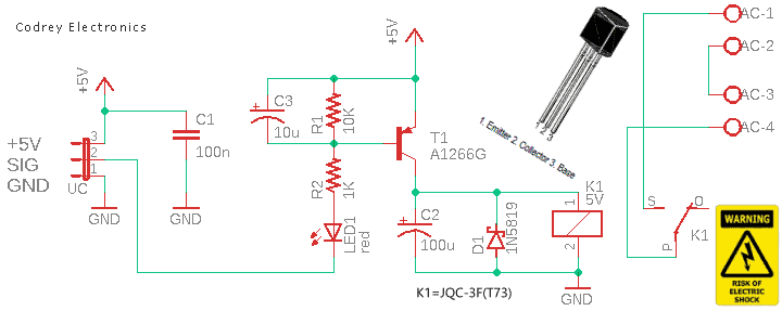
The circuit shown in the schematic below includes the components that are needed to build your own poor man’s smart plug (v1). So, instead of reverse engineering some unbranded fancy (and often dangerous) commercial smart plugs, try doing it the old-fashioned way by putting a dedicated relay module in an electrical box. Ready to jump in?
Apart from the AC230V high-voltage power input cable, the smart plug requires a 3-wire low-voltage microcontroller interface. That is:
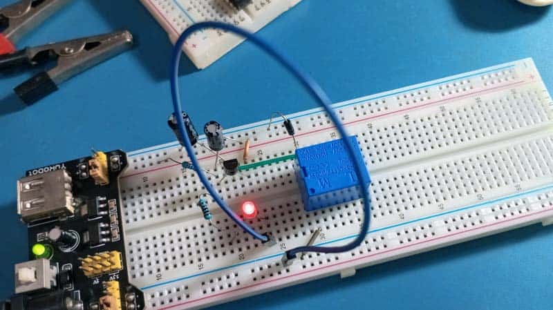
- VIN (Red): +5V from the microcontroller board
- GND (Black): 0V/GND common connection
- SIG (Blue): 0V/5V signal from the microcontroller board
Note that to turn on the smart plug, the SIG input must be set to logic LOW (0V) by the microcontroller, and to turn off the smart plug, it must be set to logic HIGH (5V).
Back to the schematic, there are only a few discrete components required, and the overall cost is very low, so this would be a good candidate for simple hobby electronics experiment.
So, the circuit has a 5VDC/70mA coil relay (K1), a A1266(G) PNP transistor (T1), a 1N5819 Schottky diode (D1), and a few other backing components. Note that even a cheap PCB relay nowadays can handle 5A-10A loads at 240VAC.
Essentially, the PNP transistor is used to energise the relay’s coil with the requisite voltage and current. The resistor (R1) between the base and emitter of the transistor would ensure the transistor is fully off when there is no signal input, rather than having a floating voltage induced.
Essentially, the PNP transistor is used to energise the relay’s coil with the requisite voltage and current. The resistor (R1) between the base and emitter of the transistor would ensure the transistor is fully off when there is no signal input, rather than having a floating voltage induced.
The magic in making a transistor switch work properly is to get the transistor in a saturation state. For this to happen you need to know the maximum current for the load to be driven and the minimum hFE of the transistor.
For example, if you have a load that demands circa 70mA of current and a transistor with a worst-case hFE of 70, you can then calculate the minimum base current required to saturate the transistor as minimum base current = 70mA/70 = 1mA. In practice, it is best to set about 30% more base current than actually required, so count it as 1.3mA to ensure your transistor switch is always saturated. So, now you can calculate the value of the base resistor as RBASE = VSUPPLY/(ILOAD/hFEMIN x1.3).
Most general purpose PNP transistors with a minimum hFE of say 50 to 100 could be used in place of the A1266 transistor. The 1N5819 flyback diode across the 5V relay coil is to conduct the current generated by the de-energizing coil back across the relay coil.
Generally, the flyback diode should have twice the voltage across the relay when it is energized, and a surge current rating at least that of the relay current. Although a Schottky diode is used here (as it has the lowest forward drop and the fastest reverse voltage recovery), it is okay to use the regular 1N4007 power diode as the flyback diode.
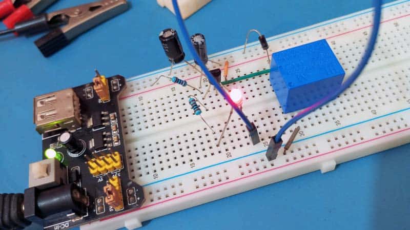
The photo shows the circuitry above on a breadboard. In this breadboard example, the breadboard power supply module, on the far left, takes 9VDC as input from an external 6F22 9V battery and delivers regulated 5VDC to the breadboard power rails. Also, I simulated the TTL input signal (logic-low) simply by shorting the input point to the ground rail of the breadboard (I am just too lazy at times, ha ha).
Now it is time to build your own smart plug…
See, you can easily make the entire electronics in an easy to use module form by using a piece of perfboard. And, there are a number of ideas for how to finalize the construction of your portable smart plug. Anyway, if you want to keep things small and robust, opt for a rigid plastic electric box (see below) as the enclosure as it should make the final build more resilient to being knocked around over time.

If everything is wired properly and attached securely, this should not be necessary but with the 3-pin power socket wired and all things in place, you can wrap up the perfboard setup by sealing all of the exposed electronics.
Remember, before taking your homemade smart plug for a test drive, take some time to triple-check that the construction is intact and nothing is unsafe. Never forget, high voltage is fatal forever!
Jumping to a quick conclusion, Thankfully all of my preflight tests came out clean and I was able to proceed. So, I hooked up my bread toaster and watched with glee as it switched on and off under the control of a microcontroller board. Mission accomplished.