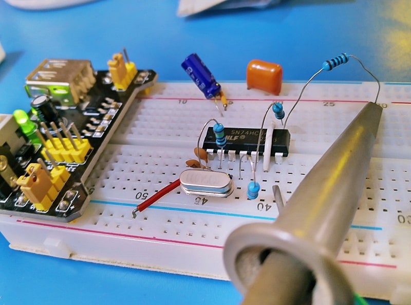
This post describes the construction of basic crystal oscillator. The key parts in the experimental setup are a KDS4.000 quartz crystal (4.000MHz) and a SN74HC04N hex inverter IC.
It should be easy to use an inverter gate to create a simple oscillator, and with a quartz crystal it should be possible to get the desired oscillator frequency. The below schematic resembles a design that is everywhere.
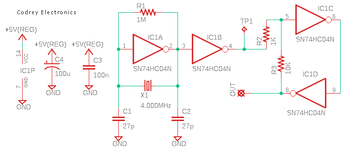
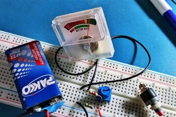
Here, the first inverter (IC1A) runs the crystal, and the second inverter (IC1B) works as a buffer. For many experiments, the output from the second inverter appears at the test point TP1 will be fine. Anyway, next two inverter gates (IC1C & IC1D) with a little dc feedback around them forms a Schmitt trigger, and simply delivers the “optional” final output (OUT). Although not a good practice, I built my prototype using a breadboard, powering it from the 5V breadboard power supply, and it does seem to work.
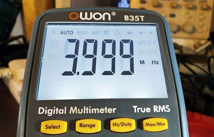
Below is a reading from the frequency counter of my Owon B35T digital multimeter.
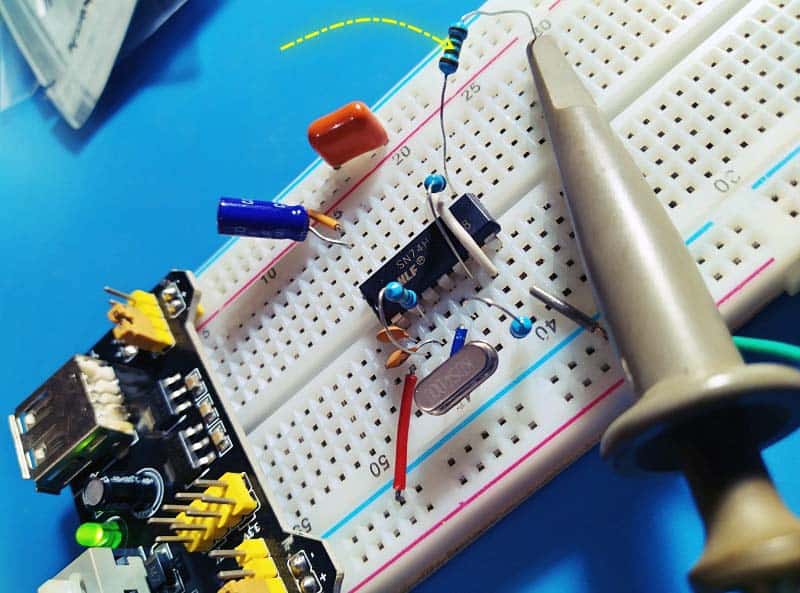
However, without any termination the output waveform is not nifty, that means, strong spikes on the positive and negative edges. So, my quest became finding a way to resolve it and enhance the square wave signal, and finally I got a somewhat sensible waveform when a 100Ω resistor is inserted between TP1 test point and the 10x oscilloscope probe during measurements.
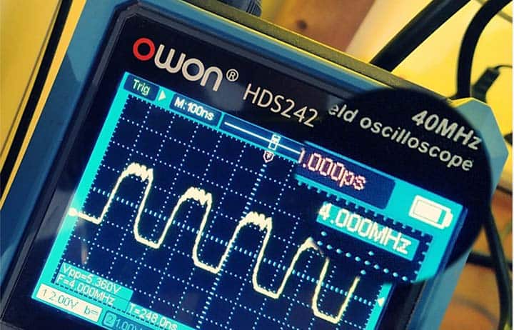
Here is a snap of my Owon HDS242 handheld oscilloscope display:
Back to the design, the first inverter is loosely a linear amplifier that generates an analog signal – it will be more of a sinewave rather than a square wave. In principle, following the first inverter with just another inverter delivers a proper square wave. It is a done deed!
As an aside, it is so easy to get an oscillator, but if you do not tie the inputs of unused inverter gates to a defined logic level then it may happen all by itself, some of the gates may start to oscillate and upset the rest of the setup.
The main goal of this experiment was the construction of a basic quartz crystal oscillator circuit, using jellybean parts. In the designed prototype, a 4.000MHz crystal is used, and a 74HC04 CMOS inverter, biased in the linear region, serves as the core of the oscillator circuit. Needless to say, for real-world applications, this breadboard mock up is neither suitable nor recommended.
Well, it is always nice to learn something new and even better to be able to build on what you learned. Have Fun!