In this short post we will again take a nimble look at electromagnetic relays and the electronics associated with them.
As we all know, an electromagnetic relay is a simple electromechanical switching device that uses an electromagnet to turn the switch on or off. The best part is that you need very few simple components to make it work in an electronic system!
Simply put, a load wired to the output of a relay can be connected and disconnected by turning a switch on and off. Also, the relay can be controlled by a TTL or CMOS signal if accompanied by a suitable solid-state switching element such as a BJT or MOSFET (see figure below).
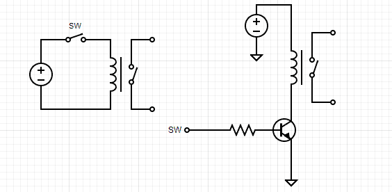
However, in the latter case, a flyback diode is essential in antiparallel with the relay coil as shown in the figure below.
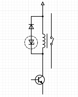
A flyback diode is any diode connected across an inductor used to eliminate flyback, which is the sudden voltage spike seen across an inductive load when its supply current is suddenly reduced or interrupted.
The selection of the flyback diode (freewheeling diode) is based on the working voltage and working current in the energized relay coil. If you want to know how to roughly determine what is required, just select a diode with a reverse voltage rating (PIV) a bit higher than the relay coil operating voltage and with a forward current rating greater than or at least equal to the relay coil operating current (usually circuit designers put in a generous safety margin in these ratings).
The 1N400x family or similar diodes are commonly used for this purpose as they are cheap, moderately fast, and have a high enough reverse voltage rating and the current capacity needed for the application.
Also note at this point that using the flyback diode in this way slows down the turn-off time of the relay, sometimes by several milliseconds. That is, with just a flyback diode in the setup, there is enough coil current maintained to keep the relay energised for some time after the driver transistor turns off (note, the release time is a combination of electrical and mechanical effects).
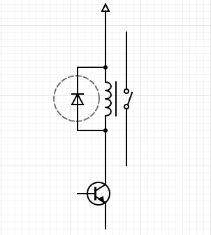
So, you can use a regular diode and a zener diode together as shown below to get some sensible betterments.
The most common practice will be to use a zener rated for the same voltage as the relay’s coil and supply. However, it is only by experimentation that you know the effects of different values and the limitations that each imposes (more on that in another post).
Now a glance at the relay terminology:
- Operating Voltage: The voltage by which the relay performs to the desired function
- Nominal Coil Voltage: The voltage by which the coil is designated and to which certain operating characteristics of the relay are related
- Coil Resistance: The total terminal-to-terminal resistance of a coil at a specified temperature
- Coil Power Dissipation: The amount of electric power consumed by a winding
- Normally Closed Contact (NC): A relay contact pair that is closed when the coil is not energized
- Normally Open Contact (NO): A relay contact pair that is open when the coil is not energized
- Relay Operate Time: The time interval from coil energization to the functioning time of the last contact to function
- Relay Release Time: The time interval from coil de-energization to the functioning time of the last contact to function
- Contact Switching Rate: The velocity at which contact switching occurs
Further Info on Relay Terminology
What is more, one common electrical characteristic that is specified of relay is the pick-up and drop out voltage.
The pick up voltage, also defined as pull-in voltage or must operate voltage, is the value at or below which all contacts must function. Likewise, the drop-out voltage, also defined as release voltage or must release voltage, is the value at or above which all contacts must return to their de-energized position.
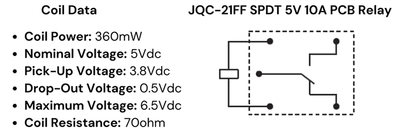
As you can see in the below datasheet snip, pick-up voltage of a JQC-21FF SPDT 5V 10A PCB Relay is 3.8Vdc while its drop-out voltage is 0.5Vdc.
Finally, let us build an exceedingly simple fun project using a commonly available SPDT relay (Form C Relay).
Note at this time that relays are classified by their number of poles and number of throws. For example, a SPST (single-pole single-throw) relay has one pole and one throw.
Also, relay forms are categorized in a ‘short hand way’ by the number of poles and throws as well as the default position of the relay. The following lists three common relay forms.
- Form A: SPST relays with a default state of normally open
- Form B: SPST relays with a default state of normally closed
- Form C: SPDT relays that break the connection with one throw before contacting the other (break-before-make)
The schematic below represents a simple setup for an electromagnetic/mechanical vibrator. The vibrator allows rapid pulses to be created from a dc source such as a storage battery.
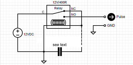
The basic function of this electromagnetic/mechanical vibrator is to chop a low battery voltage into a square wave like pattern (see the random oscillogram below) such that a suitable step-up transformer setup can then generate ample voltage for some high-voltage AC applications.
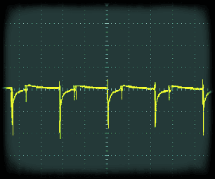
Similar vibrators were very common up until transistor revolution, for use in certain mobile devices where DC needed to be transformed into much higher AC (or DC) voltages demanded by them. Simply put, the low voltage DC enters the vibrator, which contains a relay that makes and breaks the relay contacts rapidly, chopping up the DC.
The optional capacitor (a 1uF nonpolar type for instance) shown in our schematic can drop-off the operating frequency of the relay by holding its NO state longer than the NC state. However, the actual shape (and amplitude) of the output pulse is strongly dependent on the type of relay used.
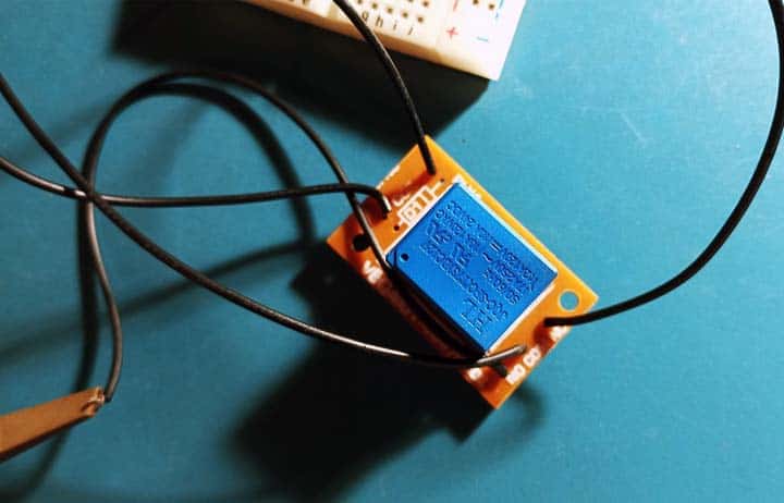
My quick experiments were done with a JQC-3F(T73)12V PCB Relay (The waveform frequency was then loosely 1kHz).
Keep in mind, since it occurs so fast, the relay vibrates or buzzes. Also, making and breaking of the current at the relay contacts are accompanied by sparking. Naturally, the sparking shortens the lifespan of the relay contacts and causes radio frequency interferences as well.
That is all for now. I bet you have not exploited a regular relay this way. So, give it a shot!