We all know that a reverse biased silicon diode can be used as a make-do temperature sensor (https://www.codrey.com/learn/bjt-diode-temperature-sensors-a-quick-walk/).
But let me remind you again, a silicon diode, when reverse biased, will introduce a certain leakage current that happens to be proportional to the junction temperature.
Well, this little post demonstrates how the 1N4148 fast switching silicon diode can be exploited as a temperature sensor!
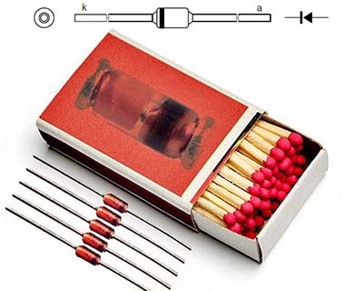
The 1N4148 is a high-speed switching diode fabricated in planar technology and encapsulated in hermetically sealed leaded glass SOD27 (DO-35) package. It has 4ns maximum switching speed and 100V maximum continuous reverse voltage. Also, the maximum repetitive peak reverse voltage is 100V, maximum repetitive peak forward current is 450mA, and continuous forward current is 200mA. Looks good!
I recently read on an audio forum that 1N4148 diodes have enough photosensitivity to cause hum, meaning that the photosensitivity of glass diodes often induces undesired low frequency noise in certain open-frame audio circuits.

Actually the IN4148 diode has enough photosensitivity to cause hum, but not as much as necessary to use as a photocell because its sensitivity is more in the infrared region than the visible spectrum. However, although manufacturers do not characterize 1N4148 diodes as temperature sensors, interestingly they can be used in that way.
Talked enough, now let us try to do it in some maverick ways, that is, set up small and cheap silicon diode-based temperature sensor/indicator circuits using handier components.
In principle, forward voltage drop (VF) of a silicon diode is 0.6V or 0.7V, but it actually depends on the current flowing through the diode, and the temperature. So, when you keep the current constant and read the forward voltage you have got a temperature sensor yourself. The response will be -2mV/°C typical which can vary a tad across diodes though.
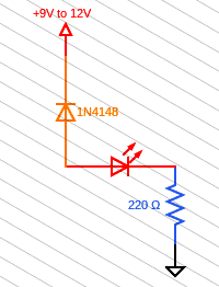
The quick setup can be as simple as shown in the figure below. A regular resistor is all that needed here because the forward voltage of the diode does not vary all that much, so the current through the resistor is almost constant.

In this way, just a silicon diode and a regular resistor linked to the ADC of a MCU is sufficient for a make shift temperature monitor setup. Since the 1N4148 is a jellybean small-signal diode that comes in a non-melty glass case, it is okay for the purpose when used with a 10KΩ series resistor (of course dependent upon the supply voltage).
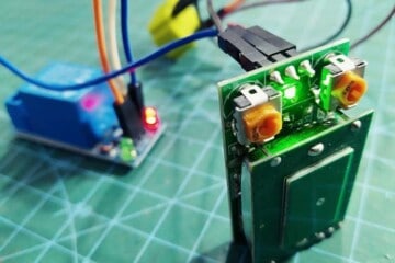
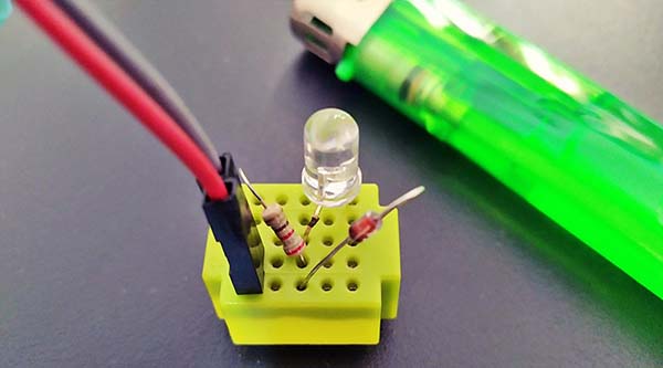
Below is one quick and dirty practical circuit to prove the concept in a different way but at a bare minimum cost.
When you heat up the 1N4148 diode with a cigar lighter, the leakage current will turn on the low-current red LED. But close proximity of the high-temperature flame (>200°C) might harm the diode in a very short period of time.
Note that most silicon diodes (non-military grade) available nowadays I have looked at are limited to 175°C absolute maximum junction temperature (Tj). Perhaps advertent application of a high temperature silicone sealant to act as a heat spreader for the diode will be a life saver.
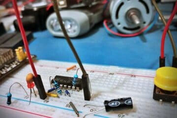
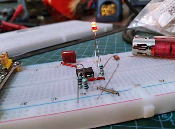
Below you can see the breadboard setup of an LM358 op-amp based circuit that can double (x2) the input voltage as configured. Without further ado, I wired up a 1N4148 diode as shown in the next schematic to make an odd overtemperature indicator (instead of being configured the op-amp as a comparator).
This is the schematic (v1):
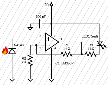
And it worked well. When the 1N4148 diode is sufficiently heated the red LED in the circuit will light up. Again, I used a cigar lighter as the heat source.
A simple variation of this circuit would allow the LED to announce an overtemperature condition only when the temperature exceeds a certain threshold. To achieve this you must configure the op-amp as a voltage comparator. Also, its front-end circuitry must be optimized to match the characteristics of the silicon diode sensor. I will not go into that now as many of you know how to do it well. Otherwise drop a comment here.
In conclusion, you can experiment with the fun ideas presented here as is, or give them a clever twist with your own ideas. It is up to you. Finally, feel free to point me to interesting resources on poor man’s way of accurate temperature sensing and I will have a look. Cheers!