It’s damn sure, there’s plenty of old optical and magnetic disc drives (CD/DVD/HDD) in every electronics/hardware hobbyist’s junk box. Sadly it’s known to few people that such disc drives are rich and cheap sources of (otherwise costly) brushless direct current (BLDC) motors. Here’s a prefatory article to shed some light on the revival tricks of that unheeded play!
The Architecture
While I was doing one project with a common hard disc spindle motor, I found that it’s a sensorless type three-phase brushless dc motor. After some more research, I came to understand that most of the hard disc spindle motors are three-phase sensorless, brushless dc motors. The three coils are star-connected internally and a common point is also provided, having a total of four connections. Unlike a brushless dc motor that uses hall-effect sensors to detect the motor shaft/rotor position, but like the trick used in an RC model motor, the motor shaft/rotor position is detected using the back-electromotive force (BEMF) generated from the no driven coils.
Obviously, here a back-emf controller circuitry is essential to ensure correct timing sequence of the drive waveforms for a healthy and nice commutation. Take note, the process of energizing and de-energizing the coils to keep the rotor spinning is called commutating. An advantage of the brushless dc motor is that the commutation occurs electrically, i.e. without any mechanical interaction between its rotor and stator. This makes the brushless dc motor very reliable and relatively cheap to build.
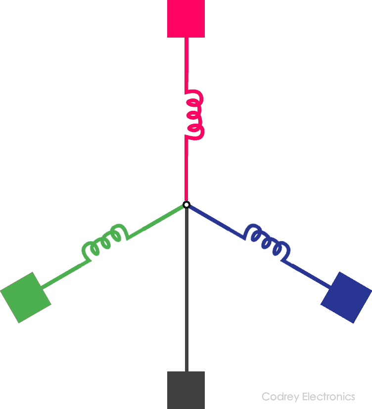
In a nutshell, a sensor-type brushless dc motor has three built-in hall-effect sensor chips to observe the motor shaft/rotor position. However, a sensorless brushless dc motor doesn’t have any internal sensor chip for position detection as its commutation is based on the back-emf introduced in its stator windings. When the motor rotates, each winding generates 120° out of phase back-emf pulses similar to the output signals from the hall-effect sensors in a sensor-type brushless dc motor (but they’re asynchronous with the hall-effect sensor signals -phase shift of 30°). In every driving sequence of a sensorless brushless dc motor, two windings are energized and the third one is floated (left opened), which is used to monitor the back-emf voltage (the back-emf voltage in windings increases when it’s connected to power supply and decreases when it’s connected to the return path). So the combination of all the three zero cross over points can be used to generate the right driving sequence.
The back-emf voltage zero cross over points can be detected using various methods. Interested readers can refer this official documentation to learn more about sensorless brushless dc motor control techniques – http://ww1.microchip.com/downloads/en/appnotes/00970a.pdf and/or https://www.digikey.com/en/articles/techzone/2011/oct/learning-sensorless-brushless-dc-motor-control-the-easy-way
Hard Disc Drive (HDD) Motor Hack
Since most of the hard disc drive motors today had 4 connection terminals, try measuring the resistance between the various terminals to find the motor pinout. When you have the common terminal, you can easily figure out others because resistance from the common terminal to each of the three others should be the same at all times. Frankly, I didn’t know what others were doing but finally locked on this idea.
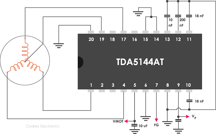
When it comes to the driver part, TDA5144AT is a good old driver chip for 4-wire (3-phase) BLDC motors. Once again, note that 4-pin BLDC motor is just a standard 3-phase motor wired in Star (or Y) configuration with its center tap brought out. The TDA5144AT is a bipolar integrated circuit used to drive 3-phase brushless DC motors in full-wave commutation mode (three push-pull output stages) with BEMF sensing technique to sense the rotor position. This IC also contains an uncommitted transconductance amplifier (OTA) that can be used as a control amplifier, capable of directly driving an external power transistor. Shown next is an Application diagram of TDA5144AT without using the operational transconductance amplifier.
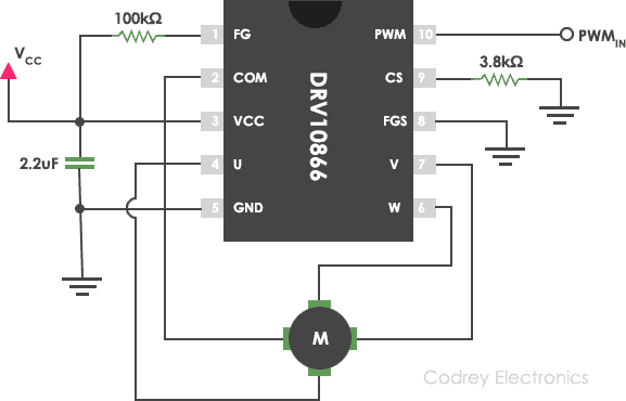
DRV10866 from Texas Instruments is another fantastic driver chip for 4-wire sensorless BLDC motors. This 3- phase, sensorless motor driver IC is integrated with power MOSFETs capable of catering drive currents up to 680mA (peak). DRV10866 also has an open-drain FG (or FG/2) output to indicate the motor speed. If the FGS pin (pin 8) is connected to GND, the FG output (pin 1) has a period equal to one electrical cycle (FG), and the same output has a period equal to two electrical cycles (1/2FG) if its connected to VCC. See typical application schematic shown below:
However, Texas Instruments DRV11873 is another great driver chip with more useful features. DRV11873 offers two driving mode (high speed motor and low-speed motor) with a dedicated pin for setting the rotation direction. The motor speed can be adjusted via PWM signal or input supply voltage, and the maximum driving current can be limited via an external sensing resistor. See the simplified schematic… Pretty cool!
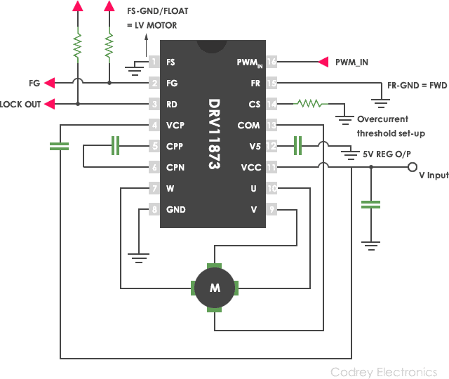
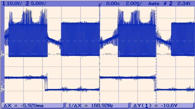
Following oscillogram shows the FG output (pin 2) taken while running a hard disc drive motor by a home-made (and dirty) DRV11873 breakout board. The PWM was 100% (zero-modulation) at that time because the PWMIN (pin 16) was left floated. Later, the author successfully tested his setup with the help of a 555IC-based PWM generator (25kHz/5% – 90%)!

What’s Next?
It’s sincerely the case that the above mentioned dedicated sensorless brushless 3-phase dc motor driver chips are unfortunately within the easy reach of an average electronics hobbyist (even many prominent sellers are sometimes poor at stocking any of the interesting chips we want to play with). On account of this, I’m building an easy driver for sensorless brushless 3-phase dc motors. Without much doubt, you can see it as a diy article coming after a couple of weeks. Stay tuned…
Note: The above circuit designs are taken from official datasheets and publisher redesigned for better view.

Hi,
Please, How do I reuse LCD of DVD players?