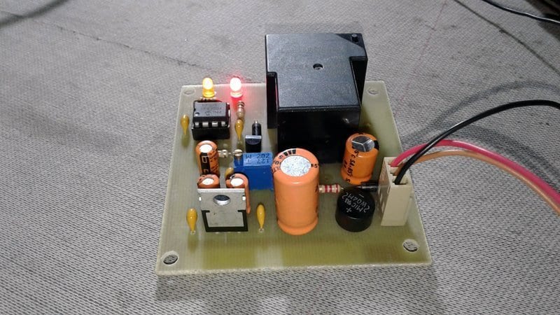
In yesteryear I’d designed and developed an AC230V over voltage protector switch based on the popular PIC microcontroller PIC12F675 (shown below is the photo of that prototype). The electronic switch can be used to safeguard electrical appliances running on household AC230V mains supply from unexpected over voltage mishaps. Here I’m introducing another version of the same design naturally with little hardware and software improvements to ensure a nice performance in almost all situations!
Hardware
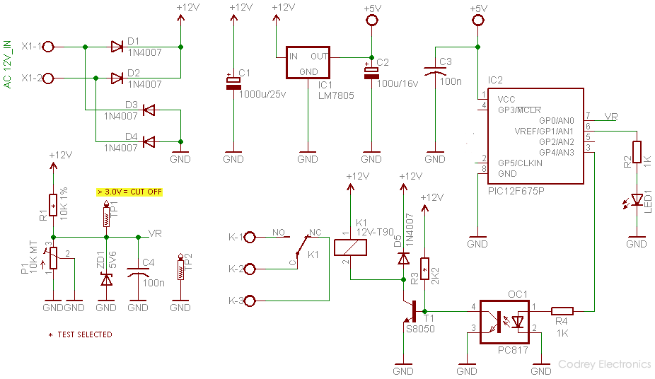
As can see in the given schematic, the circuit works on unregulated 12 V dc supply but there’s an onboard 5V linear regulator (IC1-LM7805) as the power supply of the microcontroller (IC2-PIC12F675). Pin 7 (GP0/AN0) of the PIC12F675 microcontroller samples the unregulated dc supply input available through the adjustable potential-divider network R1-P1. The 5V6 zener diode (ZD1) in the network is for input protection of the microcontroller whereas the 100nF capacitor (C4) is to clean the sample to some extent. Pin 3 (GP4/AN3) of the microcontroller drives a 12V/T-90 type electro-magnetic relay (K1) with the help of an opto-coupler PC817 (OC1) and a small-signal transistor S8050 (T1). The opto-coupler is added deliberately to implement potential expansions of output/driver part of the basic design in near future. The red indicator (LED1) is a simple system status indicator.
Software
The source code cooked in mikroC PRO for PIC is not included here because of some commercial reasons (I’d like to mold this as an end-user product). Anyway, you can use the ready-to-burn hex code given here to complete your own prototype. Keep in mind, this obviously needs an appropriate PIC programmer (PICkit2/PICkit3) to upload hex code to the PIC microcontroller.

Calibration
After the construction of the entire electronics, connect the secondary of a good-quality 0-12V/750mA step-down power transformer to the input points (X1-1 & X1-2) of the circuit, and power the transformer up from an ac variac (autotransformer) initially dialed to AC230V. Next, ensure that LED1 is in lit condition, and K1 is in an energized state. Now feed a slightly higher ac input (~250V) to the power transformer by varying the knob of the variac, and adjust trimpot P1 slowly until K1 gets de-energized (but returns to the energized state again when ac input falls to its normal level). Recheck your calibration twice or thrice, and finally paint-lock the trimpot to finish the calibration process. Thereafter, you can connect the output load through common (C) and normally-opened (N/O) contacts of K1. That’s all for now!
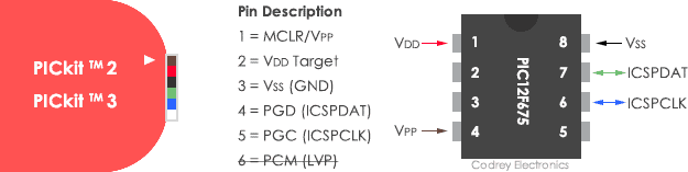
Following is the PICkit 2/PICkit3 to PIC12F675 connection diagram to help those don’t have a programming adapter in hand. I hope that you leave learned something and have fun with this presentation. Carry on…


Ready-to-use Hex code for this project can be downloaded from Author’s Google Drive!
Link – https://drive.google.com/open?id=1cAmripUNMqzFEC6fnCWuFgSs4JJfKE39
File download link problem please link sent my email address
Naresh, we’ve reuploaded the file you can download it from here: https://www.codrey.com/wp-content/uploads/2020/09/CD-OVP-Hex-Code.zip
Hi, Good day! please help me with hex code addition as well as hardware needed for adapting the circuit to do the uvp (under voltage protection) for a voltage below 190vac. Your design is excellent!
Thank you.
Regards,
Imo
@Imraan Desai: Your request was heeded and I’m glad to help you. But it will take some time because of some things beyond my control. Perhaps, you can see a new “power supply supervisor” diy project (with more features including customizable uvp & ovp) within a few weeks. I’ll try to include the complete source code and hex code in that article. Thank you for your keen interest in my little projects. All the best!
Hi TK,
Thank you. Much appreciated.
Regards,
Imo