And now another interesting little project. After seeing numerous online projects I decided to build my own simple NiMH battery charger circuit using NiMH batteries because a bunch of GP2100 series NiMH cells are lying on the shelf. Technical Specification of the NiMH cell is given below:
- GP 2100 series NiMH Cell
- 2V minimum 2000mAh
- Standard charge 16hrs at 200mA
According to PowerStream (www.powerstream.com), NiCad and NiMH batteries are amongst the hardest batteries to charge accurately. The cheapest way to charge a NiMH battery is to charge at C/10 or below (10% of the rated capacity per hour) for 15 hours, and the minimum voltage to get a full charge must be set to at least 1.41 volts per cell at 20 degrees C. This “overnight charging” method does not require an end-of-charge sensor and ensures a full charge.
The pretty simple schematic introduced here can charge a pair of Nickel-Metal Hydride (NiMH) cells overnight at a pre-defined current rate just above 200mA. Since NiMH cells require a constant current (cc) to be charged the right way, I pieced a simple constant current source with the help of some low-cost discrete components. Let’s see that:
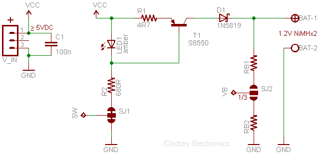
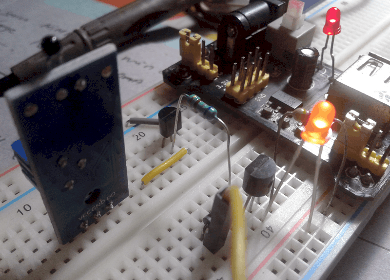
The core circuit is well-known and had been around for a long time and is probably the simplest design idea that is able to provide a constant current for connected load. Here LED1 (amber/orange) provides a fixed voltage of around 1.8V, the same drops on the base-emitter junction of T1 (S8550) and resistor R1 (4.7Ω). Value of R2 (680Ω) is chosen in a way that it can cater enough current to LED1 and T1. The given circuit configuration gives a constant current value that crosses the 240mA mark. In order for the circuit to work properly, here the input voltage (Vin) needs to be at least 1.8V higher than the optimum voltage required for two NiMH cells in series. This calls for 1.8V+2.8V =4.6V, but when taking D1(1N5819) into account this spells a minimum value of 5V.
As you might be noticed there’re two solder jumpers (SJ1& SJ2) included in the circuit. It’s intentional as it will enable the core circuit to be controlled (optionally) by a small microcontroller, such as for providing charger on/off control. Okay, straight off to that trick:
End of Charge (EoC) Detection
Although not very crucial for overnight chargers, you can add an end of charge detection/charge termination circuit with the design described here. There’re two termination methods work well for NiMH batteries: dT/dt and –dV/dt. dT/dt measures the temperature rise at the end of charge. After the battery is fully charged it starts new chemical reactions in order to absorb the unneeded current and this process heats the battery. The sudden increase in temperature rise can be used to terminate the charging process. Another effect of the above said chemical reactions is to depress the voltage of the battery slightly. If we can detect this voltage depression i.e. Negative Delta V (–dV/dt) – maximum peak voltage followed by a sudden drop of about 20mV – we can use this signal to terminate the charging process. However, the most practical method is the first one (dT/dt) because the voltage depression in a NiMH battery is smaller and harder to detect and many NiMH batteries give slipped peaks early in the charge cycle.
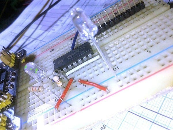
In short, we can build a smart NiMH charger by modifying the given core circuit with a small thermistor and microcontroller for implementing effective charge termination (with or without a trickle charge option). Needless to say, I’m working on it and more coming soon. Stay tuned!
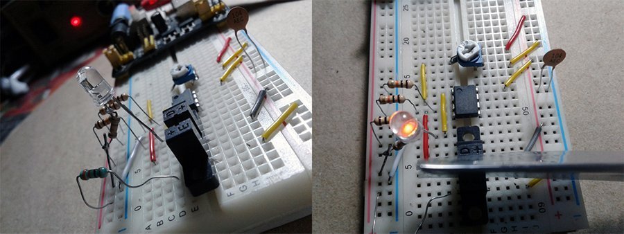
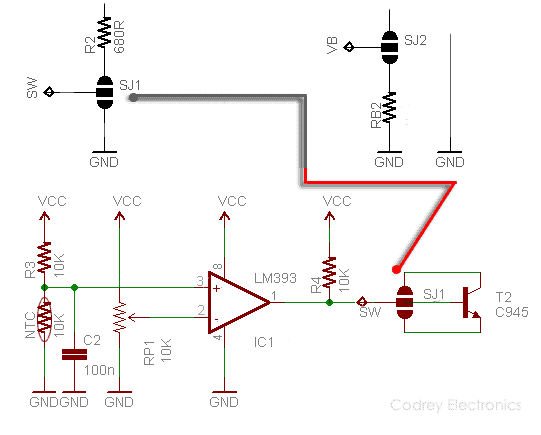
Meanwhile, interested guys can try this experimental circuit (see next image) before going for the microcontroller version. All needed is just assemble the add-on circuit on a piece of zero PCB and connect its switching transistor to the opened-solder jumper SJ1 as pointed. Note that the 10K NTC thermistor must be in direct contact with the cells being charged, and adjust the 10K trimpot (RP1) to disable the charger circuit when battery temperature goes above 33 degrees C (approximation). One drawback of this idea is that when cell temperature drops the charger will turn back on. Fortunately, there’s a way to clear this issue – reveal later…
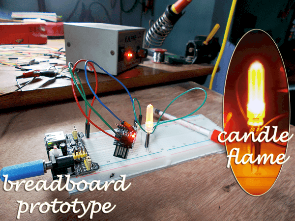
And, using the charger is easy. Just plug it into a 5VDC power supply/USB port and connect two NiMH cells you want to charge. Ensure that LED1 extinguishes when charging is complete. Use theoretical and empirical methods to fine tune your charger circuit. I want to see results!