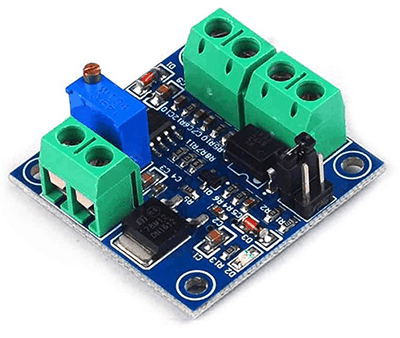
Late month I’d got an order from my neighboring client to build a pulse width modulation to dc voltage converter module that’s compatible with common microcontrollers and PLCs. Since it’s a fussy time for me I ordered a readymade module, the so called “PWM to Voltage Module”, from Amazon (see the pic) and handed over to him. Later I discovered that it’s a mere piece of electronics trading at sky-high prices. So finally I plotted the (minimal) design of a new module for the time to come and succeeded with great results in the end. A happy outcome!
Brief Overview
Since the pwm to voltage converter converts inputted PWM digital signals into 0 to 10V analog voltage it can be used as the switching interface for PLC or and other microcontroller based controller/driver boards. Here, the output voltage can be regulated by varying the duty cycle of the pulse width modulation. On paper, pulse width modulation (PWM) is a technique of encoding a voltage onto a fixed frequency carrier wave. In PWM, instead of varying the modulation frequency with voltage, output is merely switched on and off at a fixed frequency so that percentage of the on-time is proportionate to the signal voltage. With the help of any microcontroller that has PWM, it’s easy to output a PWM signal using the “analogWrite” function in Arduino (AVR microcontroller) for example. However this will output only a PWM signal not actual voltage. The little circuitry given here can quickly and easily convert the PWM output from a microcontroller into a voltage corresponding to the percentage of the PWM. Yes, now you will have a simple digital to analog converter (DAC) for the common microcontroller without on-chip digital to analog converter.
Design Description
Look below for the system diagram of the proposed pwm to voltage converter. As stated, the system converts 0-5V PWM signal input into 0-10V analog output. The entire system can be powered from any 15-24V (>500mA) dc power supply, and there’s an onboard auxiliary 5V regulated dc output for running external peripherals. The recommended (default) input pulse width modulation frequency is 500Hz +/- 2%.
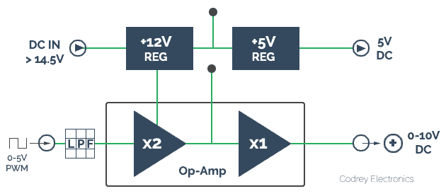
PWM is in fact a technique used to generate pseudo-analog signals. As it’s not truly analog, a low-pass filter (LPF) is required to merely smooth the signal into the ‘average’ output voltage of the PWM. In addition to the LPF, an Op-Amp with a gain of x2 is merged to raise the output voltage in 0-10V scale. The (optional) second Op-Amp, a unity gain (x1) one, is added up as an output buffer. Before we go any further we need to see the whole schematic. Sometimes it may become necessary to improve the design by tweaking the RC low-pass filter and gain setting components in the op-amp circuit. Okay, let me render the well-annotated factual circuit diagram:

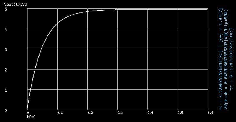
As we can see in the schematic, now we have everything we need to adjust the output voltage in tune with the input signal. As I mentioned, the LPF (R1 &C7) plays an important role here, and while this single-pole filter is very simple, opting appropriate values for the RC components comprehend some design decisions – that is to say, how fast does the filter need to respond and how much ripple can we tolerate (see addendum)? With 5.1K for R1 and 10uF C7, the resultant time constant is 51mS (fc = 3.12 Hz). Transient analysis/step response graph (fPWM=500 Hz) of the LPF used here is shown below:
Curious readers may be wondering how I calculated the above RC values. In order to pass only the dc component of the pulse width modulated waveform, a low-pass filter with a cutoff frequency much lower than the fundamental frequency of the pulse width modulation pulse should be required. I did it on an empirical basis (an acceptable trade-off to cut out unnecessary complexity and cost) because it worked like a charm. The gracious thing about the math is, counting on your measures, there are often multiple practical RC values for the low-pass filter!
Quick Tryout
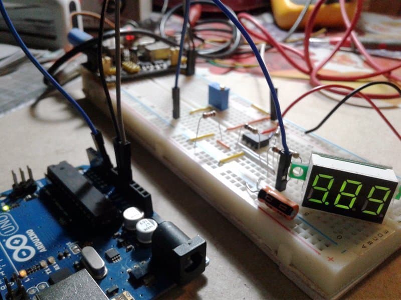
Arduino (Uno) has total 6 pins that can be configured for PWM output. The PWM signal on pin D9 (D10 as well) provides an output frequency of 490.196 Hz, so we can take it to test our prototype. Just copy-paste-upload the given test sketch, connect a multi-turn 10K trimpot at A0 (+5V-A0-GND), and feed output from D9 to the input of the pwm to voltage converter module. And then vary the trimpot to ensure that the output shifts successively in 0-10V scale. Righto?
int pwmValue = 0;
int pwmOut = 9; //D9 as PWM O/P
int trimPin = A0; //A0 as Trimpot I/P

void setup() {
pinMode(pwmOut, OUTPUT); //Set D9 as O/P
}

void loop()
{
pwmValue = analogRead(trimPin); //Read A0
pwmValue = map(pwmValue, 0, 1023, 0, 255);
analogWrite(pwmOut, pwmValue);
}
Addendum
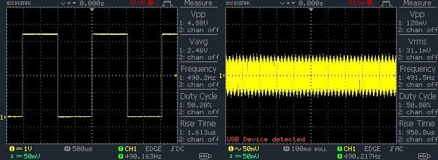
A word about ripples – in my quick experiment the LPF consists of a 5.1KΩ resistor and a 10uF capacitor. With 490Hz default PWM of Arduino, this kicks in about 31mV of ripple (0.00624×5) at the input of the op-amp converter. If this is too much for a distinctive application, it would be good to increase the pulse width modulation frequency and/or try a higher order low-pass filter. A bit hard to handle indeed!

This is realy good project.Thank you for your share. how can İ set max output analog voltage to 6.25v. Thank you for your help.
Aky:
Here, the maximum output is around 10V but you can ‘tune’ the trimpot to set 6.25V output. Or, if you want to scale down the maximum output to 6.25V (instead of the 10V) when trimpot is at its maximum sweep, try to fiddle with the code line “pwmValue = map(pwmValue, 0, 1023, 0, 255)” accordingly. You can refer this too, https://www.arduino.cc/reference/tr/language/functions/math/map/
BTW, version 2 (v2) of this project is now under preparation, so you can see it in near future. Thanks for your query!
Hello, i am interested to make this, you mentioned in a comment that v2 is coming soon, how soon, because i need to build this. Also can it be powered from the 12V power supply, it would be great if it could. My best regards and thanks for the help!
Frissco,
I’ll try to share the next part as quickly as possible. It is requested to periodically visit this page for relevant updates.
If you’ve a well-regulated 12VDC power supply handy, yes you can omit the 7812 regulator and feed your 12VDC directly to the +12V rail, that means, across C4.
Thank You!
Hello there again, how is your progress on V2 of this doing, i hope it will be out soon,becuase i really need it for my CNC to control a VFD speed settings with it. And also am i correct when i think that the change in output voltage is not linear on this. One question is would it be possible to get it to be linear change in voltage? Thanks in advance ! Best regards!
FrisscoCBR: Thanks for the reminder. Yes, it’ll be out soon, perhaps within the next month. Now I’m looking for a clever method for PWM (0-100%) to Voltage (0-5v to 0-10v) Linear conversion. I’ll update you soon. Meanwhile you may checkout this link http://www.icstation.com/voltage-converter-module-adjustable-converter-power-module-digital-analog-signal-p-12498.html
Well i looked at it, but i can not order it in my country because of coronavirus, no proper import, so i created yours and its quite good but how could i remove the ripple, because its variating to much and my VFD frequency depends on it. I would be really thankfull if you explain me in short how could i create a better low pass filter for it? Thanks in advance
Frissco CBR: You’re welocome, and thanks for your patience.
Since I’m extremely busy now, I need a bit more time to help you. Don’t be discouraged!
In the meantime, you may checkout this link http://sim.okawa-denshi.jp/en/PWMtool.php
hello out put is dc or analog cause in images its dc but in text its ac
soliropa: Go through the article again. Where you can see the final output is declared as ac in the text?
and if you have the full circuit the PWM to Voltage Module can you email it to me cause i saw the j3y transistor and PC817 Optocoupler and i dont have any ideas were to place and how to Biasing them
my email is soliropa@gmail.com
thank you.
Soliropa: I don’t have a circuit diagram of that Chinese module. Note that it’s different from my circuit published here (https://www.codrey.com/wp-content/uploads/2018/10/PWM-to-Voltage-Module-Circuit-Diagram.png).
And, I pretty much doubt that I am of any help. I’ve no idea about the circuit you’re experimenting with. First, you need to dig deep and find out why your specific circuit is not working. Questions on custom projects are better to post in an electronics forum. If so, someone else might be able to answer them right. Good Luck with your experiments!
hi i did the circuit but i need the out put 200ma cureent the i set it to load my voltage freezes i dont know how to fix it please help me here
sorry for bad english
Hi sir, nice post, I really appreciate, could you tell me why theres a optocoupler in the module, also, the trimpot in the commercial board, it is used to adjust the input pwm to fine tune the output ? thanks a lot
Hi, the c7 is really a polarized cap ? thanks sir.
Willian: C7 is a polarized 100uF capacitor. Thanks!
Willian: I don’t have the original circuit diagram of the Chinese module. I think it’s a bit different design. Anyway, I’ll try to gather the module and post a review later. BTW, an optocoupler is usually used in a circuit to provide galvanic-isolation. Thanks!
Hi, it is said that “With 490Hz default PWM of Arduino, this kicks in about 31mV of ripple (0.00624×5) at the input of the op-amp converter”, here, where you got the value 0.00624×5? Please reply as I’m new to this topic.
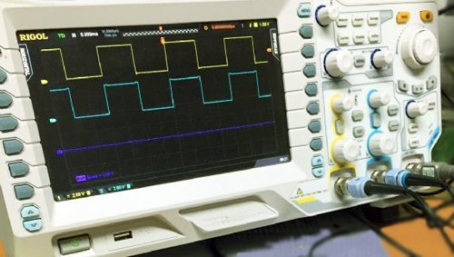
ANGEL: Sorry, I don’t have enough spare time to go back to the references for this post published 4 years ago. As you can see in the included oscillogram, the ripple voltage is about 31mV. Hope this article (www.thebox.myzen.co.uk/Tutorial/PWM.html) helps you learn more about the math behind my notes.