Camper Inverter introduced here is nothing but the minimal design of a compact dc-ac power inverter built around a couple of less expensive electronic components. This little device can serve as a portable source of AC230V/50Hz for powering small electrical appliances up from any 12V automobile battery.
- Input Voltage – DC12V (>7Ah)
- Output Voltage – AC230V/50Hz (square wave)
- Output Power – 40W to 60W (apprx)
- Output Regulation – NO
- Output Protection – NO
- Input Protection – Fuse & Diode (optional)
- Battery Protection – Deep Discharge (by the controller)
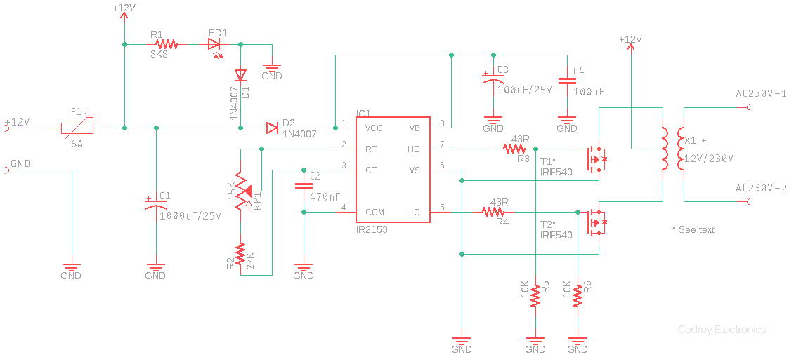
Circuit Diagram
Design Description
As can see in the circuit diagram, the key component is IR2153 (IC1) from International Rectifier which is a high voltage, high speed, self-oscillating power MOSFET and IGBT driver with both high and low side referenced output channels. Features include undervoltage lockout, programmable oscillator frequency, 50% duty cycle, and 1.5uS deadtime. Here the oscillator frequency is determined by the RC components R2-C2, and RP1. The 15K trimpot (RP1) can be used to lock the oscillator precisely at 50 Hz (or 60 Hz). The IRF540 power mosfets (T1 & T2) are driven by the output pulses from IC1.
For the inverter (output) transformer (X1), a common 5A-rated 12-0-12 transformer is used here with its secondary winding treated as primary and vice versa. Certainly we can opt for a higher-rated transformer, however, the power mosfets (and the fuse) should be changed accordingly to cope the power demand. Also note that the first 1N4007 diode (D1) is not very essential as it’s only for input reverse polarity protection. Similarly the circuit will run without the second 1N4007 diode (D2) – simply replace D2 with a 47Ω resistor.
Construction Hint
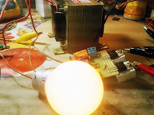
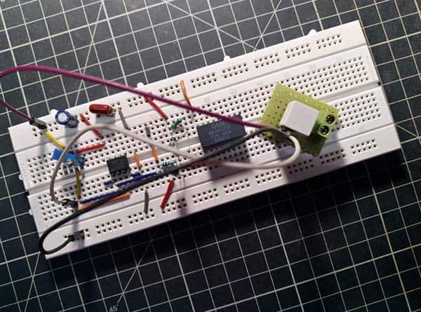
Next is a casual snap of my prototype assembled on a perf-board. But there’s still some finicky work ahead of me. Obviously a smart enclosure gives the camper inverter a polished look, and I’m looking for a dainty one!
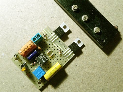
Remember, some heatsinking is needed or at least recommended for the mosfets as the mosfets might heat up when in operation. You can use a single heatsink but with perfect isolation (try a heatsink insulating kit), or freestanding heatsinks for each mosfet. In the latter case ensure that the mosfets must not touch each other, and/or never make an accidental contact with the ground rail.

Setup Diagram
Now is the good time to look up the proposed setup diagram. Be careful, you’re going to handle high-current dc supply and high-voltage ac supply at the same time!
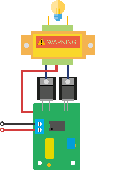
Warning: The final output voltage is lethal. Never try to touch both output terminal at the same time. High voltage experiments are dangerous forever. Do everything at your own risk!
Component List
•	IC1: IR2153
•	T1 & T2: IRF540 (or IRFZ44) – see notes
•	D1&D2: 1N4007 (or 1N5817) – see notes
•	LED1: LED 3mm
•	R1: 3K3 ¼ w
•	R2: 27K ¼ w
•	R3&R4: 43Ω (or 47Ω) ¼ w
•	R5&R6: 10K ¼ w
•	RP1: 15K Trimpot (multiturn)
•	C1: 1000uF/25V
•	C2: 470nF
•	C3: 100uF/25V
•	C4: 100nF
•	X1: 12-10-12 (5A)/230V – see notes
•	F1: 6A – see notes
Waves of Thoughts
The inverter takes dc input voltage from a battery and converts it to ac, and basically it switches the dc input on and off and to create an ac output. The square wave inverter is the simplest and least expensive type, however, harmonic content of the square wave results in unwanted electrical noise. Different electrical appliances will be affected to greater or lesser degrees by the square wave form of the ac. Although, resistive loads will not be affected, most inductive loads may run with a bit more noise and get warmer.
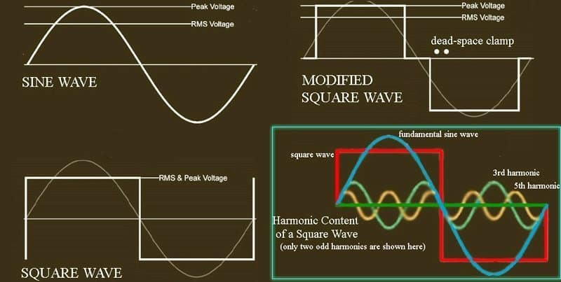
In principle, harmonics are the frequencies contained in a composite waveform, which are integer multiples of the fundamental frequency. The fundamental is at the same frequency as the square wave, and each odd harmonic is an odd multiple of the fundamental frequency. If the fundamental frequency is f then the frequency of second harmonic will be 2f and the frequency of third harmonic will 3f and so on. For example, if the fundamental waveform is 50Hz, then the 2nd, 3rd, 4th and 5th harmonic components will be at 100Hz, 150Hz, 200Hz and 250Hz respectively.
Admittedly, harmonics are especially a hard presence in many situations and it’s noticed that certain appliances may be damaged entirely by wave forms other than pure sine wave. Fortunately, with pulse width modulation (PWM) and integrating/low-pass filtering (LPF) techniques, a nearly pure sine wave can be shaped. I’ll try to include more notes on this intricate idea in a forthcoming article!