Little LED Night Marker introduced here is a simple circuit based on the common and cheap dual-operational amplifier LM358. The night marker is in fact a safety device designed to mount near obstructions in unilluminated areas as a warning device that turns on a bright flashing light source at night automatically.
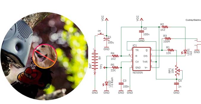
In the circuit, an ordinary LDR (light dependent resistor) is used as the ambient light sensor, and an amber LED as the winking indicator light. This low-current circuit can be powered from any dc power supply source if its output lies in 7 to 20V scale (thanks to the onboard linear voltage regulator). Okay, let me start with my simple, straightforward, and self-explanatory circuit diagram of the little night marker.

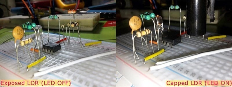
Here in this (unorthodox) design, first op-amp (A) of the LM358 (IC2) is wired as a low-frequency relaxation oscillator while the second op-amp (B) is used to switch the indicator (LED1) based on the status of the light sensor (LDR). In brief, second op-amp enables LED1 only when LDR receives low or zero light. The light detection threshold of the circuit is determined by the potential divider network (R5-R6) tied to pin 5 of IC2 so that if pin 5 can ‘see’ a voltage slightly above 2.5V, it will fire LED1 up. Perhaps, one 100K trimpot in lieu of the R5-R6 potential divider network will give more flexibility for keen experimenters (this approach has been tried by me with good results). For the onboard linear voltage regulator needed to output a steady dc voltage to the entire circuit, one TO-92 package LM78L05 positive voltage regulator (IC1) is included in the circuit. Recommended dc input voltage of IC1 is 7 to 20V for 4.75 to 5.25 dc output voltage (100mA max).
Now let me take a crude ‘theoretical’ look at how the oscillator circuit functions. As should be clear from the circuit diagram, in the ‘one op-amp oscillator’, C3 charges and discharges alternatively through R3. Whenever voltage across C3 crosses a trigger threshold, op-amp output voltage reverses to its opposite saturation limit. Thus the current through R3 changes sign, and the capacitor voltage travels toward the opposite threshold. Accordingly, the voltage across C3 sweeps between two threshold voltages as the op-amp output switches back and forth between its two output saturation limits. In principle, the voltage profile of C3 is a sequence of exponential relaxations toward the op-amp’s alternating output saturation voltages (each relaxation interrupted when a certain threshold is crossed). The RC time constant of R3 and C3 has an obvious contribution to the frequency of oscillation. Also the resistors R1 and R2 play an important role here because they can influence the thresholds.
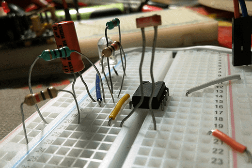
My temporary prototype was built and tested on a 400 tie-point solder-less breadboard (see above image). Proper component selection and construction method is very critical because all components have an effect on frequency, not just R3 and C3. Note that the breadboard itself can introduce parasitic capacitance into the circuit, worse with high frequencies. Also, cheap ceramic capacitors have worse stability especially over temperature, so try to use a stable type capacitor as C3.
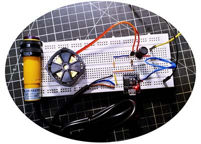
A scrap of perforated circuit board is enough for the construction of the whole circuit. After construction and successful testing, enclose the electronics in a translucent soap box (see next image) or small prototype box.
Epilogue
Relaxation oscillator, that generates a changing voltage at a particular frequency by charging and discharging a capacitor through a resistor, is certainly a good choice for low frequency generator applications. To get a better picture of how relaxation oscillators make oscillations, take a look at various online tutorials – Hopefully, google will help you to find good resources.
OK, now you have an unorthodox nonlinear analog circuit idea to start some ‘relaxation’ experiments. Take your first step by changing the value of R2 to 1K and observe LED1. Any noticeable change in its blink pattern? Similarly, add a 100K resistor from pin 3 of IC1 to GND and watch again. What’s the result with a 10n capacitor instead of the 100n (C3)?
Further, it’s worthy to expend a few hours to learn more about relaxation oscillators because its feedback strategy is applicable to many types of simple analog timing and oscillator ideas. Clearly, my circuit will perform well, still there’s enough room for improvement. Give it a good try, and let me know!