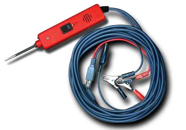
You do not need to read this post if you are willing to thoughtlessly throw away your hard-earned money to buy a car power probe that only has very cheap electronic circuitry inside. On the other hand, if you are thinking of building such a tool yourself with a handful of components, you should look at the simple design concept presented here!
Well, let us start building the poor man’s car power probe. See its schematic below.
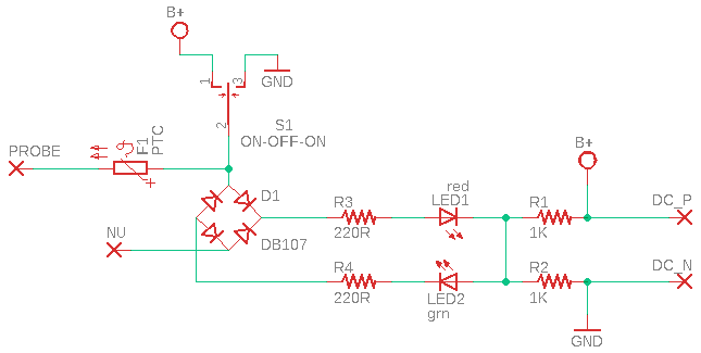
First off note that the poor man’s car power probe is a great tool for diagnosing common automotive electrical problems. Upon connecting the tester to the automotive battery, you can detect if a power lead/terminal is positive, negative/ground, or break. You can do this by probing it at a power point and observing the red and green indicators.
There is also a three-way power button to energize certain car gizmos through a resettable fuse protected automotive power supply. That is, if you feed power from the automotive battery to a dead short device, the internal resettable fuse on the car power probe will trip and thus protects the device and the tester. The tester returns to its normal state after a while, so you do not need to do anything to reset it.
Parts needed for this little project are:
- D1: DB107 Bridge Rectifier
- LED1: Red 3mm LED
- LED2: Green 3mm LED
- R1-R2: 1KΩ ¼ w Resistors
- R3-R4: 220Ω ¼ w Resistors
- S1: ON-OFF-ON (Centre OFF) Rocker Switch
- F1: Resettable PTC Fuse (see note)
To power the probe connect power leads (DC_P & DC_N) of the car power probe to the 12VDC power supply provided by the car battery (keep in mind the polarity).
Next, you can probe the car power leads/terminals to check the polarity. The red LED (LED1) indicates a positive (+) voltage and the green LED (LED2) indicates a negative/ground (0V) point.
Besides this, you can also power devices in the car like lights, horns, motors, etc with the power button (S1). Note, position 1 of S1 will deliver +12V on the probe tip and position 3 will give 0V/GND to the probe tip. Note that S1 can also be used to self-test the car power probe in short order!
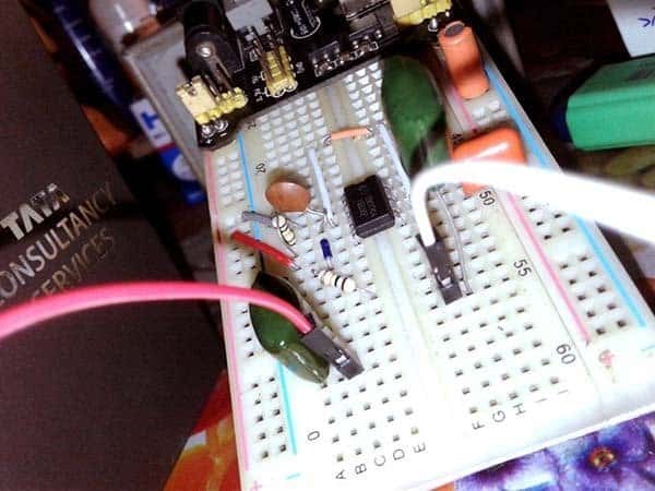
As mentioned earlier, the car power probe also has a resettable fuse to protect the tester and device under test. My breadboard prototype has a 7A/16V PTC fuse (FRG700-16F) as it was handy then but you can change it as necessitated.
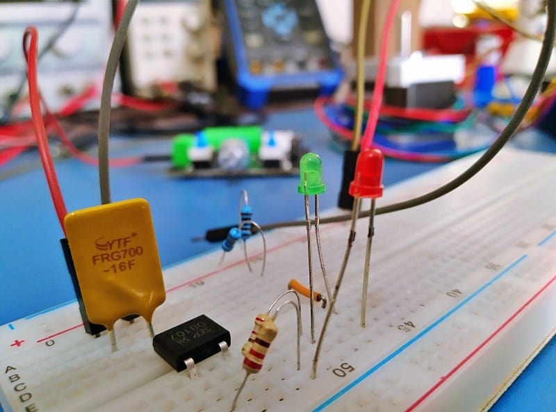
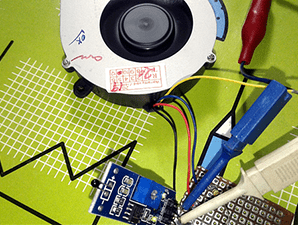
Now you can see that the red LED is active…
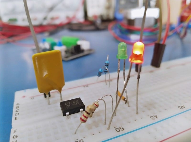
And, here is the green LED…
The power switch S1 is not included in my breadboard prototype but trust me it will work. Likewise, only a part of the bridge rectifier D1 is used in this design, the NU mark simply denotes Not Used!
Finally, follow the schematic, assemble the circuit on a flake of perfboard, and make a nice enclosure to frame-up your own car power probe. Hope you have fun!