This article covers a simple version of my portable solar power box. In use, it worked flawlessly for me. Although this is a simple version, I am sure someone will be able to improve on it.
The key parts for this pretty simple build are shown and listed below. The electronics bits are all very common and cheap as it’s easiest for you to source and much of it you already had.
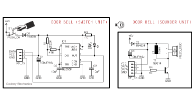
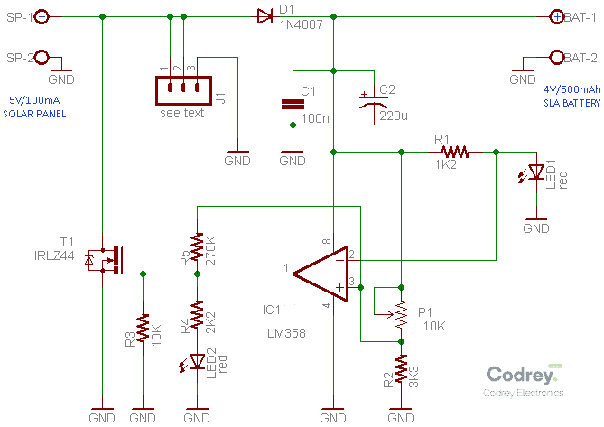
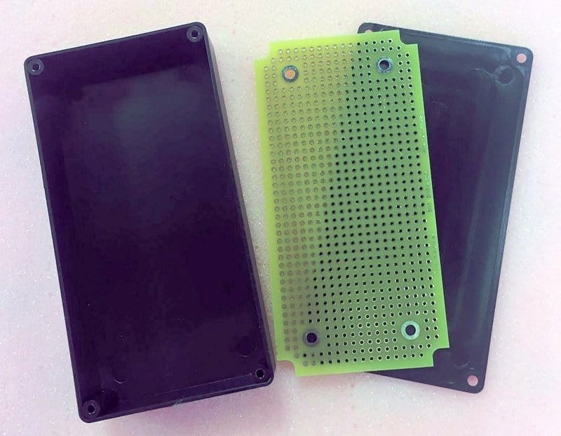
At the heart of the project is a little electronics circuitry which is in fact a tricky solar panel regulator. Frankly, it’s the basic form of a on/off type solar charge controller. Building the electronics circuitry is very simple. All components are widely available, and most can be easily replaced by other types if necessary. The entire circuitry can be built on a small perfboard and mounted in a sealed plastic project box/lunch box. However, make sure that the final build can withstand the harsh outdoor environment and a fair amount of abuse. Following is the complete schematic diagram for the simple solar power box project.
According to the basic lead-acid battery chemistry, anything above 2.15 volts per cell will charge a lead-acid battery (4.3V for a 4V battery). This also means than nothing below 2.15 volts per cell will do any charging. However, most of the time a higher voltage than this is used as it forces the charging reaction at a higher rate – the lead-acid chemistry is fairly tolerant of overcharging!
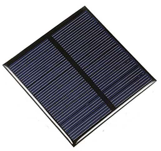
With the recommended solar panel you only get 100mA to play with. Because the solar panel sets so little power compared to the size of the battery, and the sealed lead acid battery is rather forgiving, all you require is a single diode – D1 in the above schematic – to ‘solar-charge’ the battery. One drawback of this design is the fact that the battery won’t start to charge at lower levels of sunlight.
When the sun gets up and the solar panel starts producing 5V and starts charging the battery through the 1N4007 diode (D1). As long as the battery voltage stays below the level set by the 10K trimpot (P1), the LM358 operational amplifier (IC1) will keep the IRLZ44 logic-level MOSFET (T1) off, so nothing will happen and the solar panel current will flow through the diode to the battery.
When the battery reaches the set voltage, which is nominally 4.4V, IC1 switches on T1 thus shorts out the solar panel (a condition that is quite safe here), so that the battery no longer gets charging current. After a while, when the battery has discharged enough to overcome the hysteresis of IC1, T1 is switched off again. And then the circuit will charge the battery again until it reaches the set voltage. In this way, the setup works in cycles.
Here, you need a voltage reference, which gives a (more or less) stable output voltage regardless of changes in supply voltage. As you might noticed, an ordinary red LED (LED1) is used in the circuit for the reference voltage regulator. At low currents, a typical red LED has a voltage drop of 1.6V to 1.9V, this will vary slightly with the type of LED (and its series resistor) used, though. In my prototype, voltage across LED1 (the reference voltage) is about 1.86V. The maximum DC current through LED1 is around 2 mA, set by the 1.2KΩ series resistor (R1).
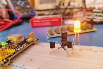
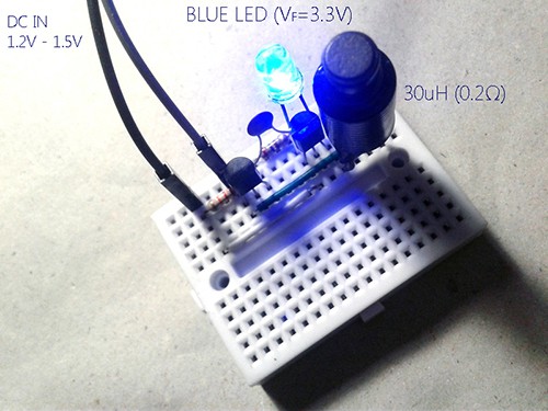
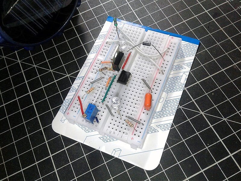
At first, I followed my usual practice and rigged up the prototype on a mini breadboard.
Thereafter I successfully wired the solar panel and the lead-acid battery and did some quick experiments.
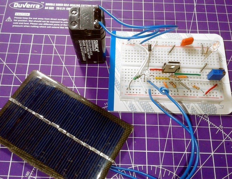
And then I cautiously moved the calibrated fabrication out of doors to test it in high noon sunlight. Believe me, it worked flawlessly!
By the way, the calibration is not very tedious, using the trimpot with a little patience it’s possible to fine-tune the setup for optimum performance. In order to proceed with the initial calibration, first of all remove the solar panel and battery, and feed stable 4.4VDC (minimum 4.35VDC) to the circuit through the battery connection terminals. Then, slowly adjust the trimpot so that the second LED (LED2) just wakes up at that voltage. Next remove the DC input and connect the battery and the solar panel, do a test in real-world and retouch the trimpot if necessary. Finally double-check the calibration, and secure the position of the trimpot screw using any appropriate glue/paint.
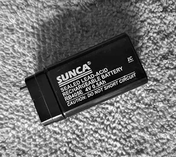
In principle, the sealed lead acid battery is a lead-lead dioxide system. The dilute sulfuric acid electrolyte is absorbed by separators and plates and thus immobilized. Should the battery be accidentally overcharged producing hydrogen and oxygen, special one-way regulator valves allow the gases to escape thus avoiding excessive pressure build-up. Else, the SLA battery is completely sealed, and hence, maintenance-free, leak-proof, and usable in any position. Number of the cells in the 4V SLA battery is 2, and the nominal voltage is 4V. As found in a datasheet, nominal capacity of the SLA battery tried here (4V/500mAh) at 20 hour constant current discharge rate (25oC) is 25mA, 3.5V. I am not a battery guru! These are simply my findings and I hope someone will be able to correct my mistakes if any.
Where to go from here?
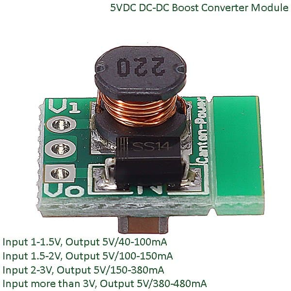
Well, now you have a handy solar power box that can deliver 4V/500mA DC output. On paper, this looks like a good idea but an impractical solution in certain situations. You can ofcourse use the solar power box to energize low-current LEDs or the like, especially during tenting or hiking. But you’ll need to put a DC-DC Boost Converter module together with the main circuitry to get a USB-standard 5VDC output. For the test, I randomly picked the $2 minuscule dc-dc boost converter module sold by Canton-Electronics. In India, you may get it from Robu.in
In this case, consider replacing the existing 500mAh battery with a 4V/1000mAh type as well. Then to fully charge the battery in full sun you need 1000 mAh/100 mA = 10 hours at 100% efficiency. Perhaps you can charge the battery for a maximum of 4 to 8 hours per day at an utmost 100mA in reality, but don’t worry, the battery will be charged at 1/10th of its capacity for days (and days) without making bubbles of gas.
To make it much better and more utile, you should go farther in this basic theme. Look, with the components shown, the circuitry comfortably welcomes a 6V SLA battery with a well-matched solar panel. For the higher voltage version, only a few parts need to be replaced by suitable ones. The rest of the circuit remains the same. If you’re really worried about overcharging after the alteration, simply plug a proper shunt regulator module into the 3-pin header (J1) – ask me, I’ll try to help you. Moreover, the IRLZ44 MOSFET can also be substituted easily by any logic-level type MOSFET you wish, as long as its RDS(ON) is low enough so that the power dissipation will remain satisfactory at the maximum current delivered by the employed solar panel.
Back to the basic design, someone might think that the op-amp is superfluous as there’s not a crucial requirement for a shunt regulator/solar panel regulator in this ‘low-profile’ design (a single can do the job well). But it’s a case of bad judgment. As pointed above, the basic design is highly adaptable so that you can reconfigure it to work with higher voltage batteries and solar panels, perhaps up to 12V or 24V. Besides, the unused (second op-amp) can be used to form a battery state indicator or output load control switch.
The core circuit is essentially an op-amp wired as a comparator. The voltage reference is quite crude, but high accuracy is not required. The LM358 op-amp is a very popular and long-lived general-purpose amplifier due to its flexibility, availability, and cost-effectiveness. The LM358 op-amp has several distinct advantages over standard op-amp types in single supply applications. It can operate at supply voltages as low as 3V or as high as 32 V. The minimum Vcc is 3V and many applications use a 5V supply with good results. Anyway, for lower Vcc, such as those in the range of 3V to 3.6V, pay careful attention to the input and output voltage ranges.
Finally, my next version is mostly ready, and I am now waiting for the enclosure to arrive in the next few weeks. I will document the new build and post the final results in the near future. Thanks for reading. Have fun with solar electronics!
Credits & References