Circuit of the Universal 1W standby LED Light introduced here is more self-contained and more flexible than many of the early designs. The circuit consists of a small Lithium-Ion (Li-Ion) battery, simple Li-Ion battery charger, and an automatic 1W LED driver with one common 1W Star White LED. Since the circuit can accept DC input in 9-12V (500mA typical) range, it’s easy to recharge the system with an appropriate solar panel, automobile battery, or ac/dc power adapter.
Circuit Diagram & Description
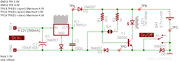
Circuit of the standby light is pretty simple and straight forward. Here, the 3-pin fixed voltage regulator L7805CV (IC1) is configured to supply a steady dc output (close to 5.6V) from an input dc supply in 9-12V range. Output of IC1 is extended to the 3.7V Li-Ion battery (BAT) through two 1N4007 diodes (D2 &D3). See there’s also a 1N5817 diode (D4) plus On/Off Switch (S1) combination in the same charger supply path. Inclusion of D4 ensures that the charging process will continue even if S1 is in off position. Similarly, D3 will disable the S8050 driver transistor (T1) – and hence the 1W Star White LED (LED1) – whenever proper dc supply (DC+ and GND) is available across the dc input terminals (Dc In). The solder jumper (SJ1) in the circuit is included deliberately to control the brightness of LED1. If SJ1 is closed (default mode), the 1K resistor (R2) is connected in parallel with the 2K2 resistor (R1) so that LED1 will give full brightness. Parallel combination of R1+R2 chips in a resistance value close to 680Ω so that LED1 will get a current around 270mA (@3.3V). Note that LED1 is a bit under-kindled (~900mW), though T1 can handle current up to 1.5A, and there’s a reason for that!
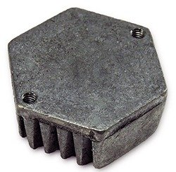
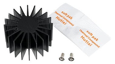
As a rule of thumb, we need a minimum of 1 square inch surface area exposed to the open-air for 1W LED on the heat-spreader, with a minimum of 0.8 inch thickness under them. Note that dropping down to 50% of the maximum power really cuts the heat a lot but does not affect the light intensity so much. Since LED1 operates here at 90% of its maximum power (by default), a good 1W LED heat sink must be required for a good run. Without an additional heatsink, temperature of LED1 in my ‘unwrapped’ prototype shot up to 44°C within 2 minutes (Tamb = 27°C). Similarly, one TO-22o heat sink is crucial for the voltage regulator chip (IC1).
Nominal voltage of a single-cell Li-Ion battery is 3.7V, but its maximum voltage is 4.2V. That’s why you see a target voltage output near 4.2V from a dedicated Li-Ion battery charger module, such as the one based on TP4056 IC. Even without the prescribed Li-Ion battery charging algorithm, Li-Ion battery in this circuit will charge smoothly irrespective of the position of S1. If S1 is closed while charging (automatic light switch mode), the target voltage is around 4.2V, however, when S1 is in open state (manual light switch mode), the target voltage drops to about 3.9V.
Construction & Transformation
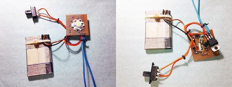
The whole electronics can be built on a small piece of square/round perforated circuit board without any undue difficulties. Try to keep the length of wires/tracks as short as possible, and ensure there’s enough room for heatsinks. Literally any 3.7V Li-Ion battery (>1000mAh capacity) can be used but it should be a type with internal protection circuitry. I’d tested my prototype with a Nokia mobile phone battery (1090 mAh/3.7V), and a standard 18650 type Li-Ion battery (1500mAh/3.7V) with built-in protection circuits. The on/off switch must be selected with great care as well, because one high-current (>500mA), low-contact resistance (< 500mΩ) slide (or rocker) type switch is highly recommended for this design (slide switch used by me drops about 100mV – a bit indisposed).
Certainly you can transform this basic system into beautiful and useful devices for stinting general/specific indoor/outdoor lighting applications. The broad list admits rechargeable (solar-ready) bicycle headlights, farmer headlamps, workbench lights, search lights, garden lights, tent lights, pathway lights, rescue lights, etc, etc.
Power LED Heatsink Maths
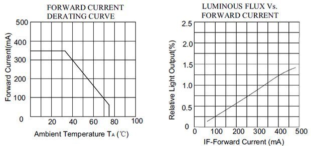
So there you have it, now you should know why you need an additional heat sink for the 1W star white LED. The star heat sink on the LED cannot fully dissipate a full 1W of heat. Therefore to drive the LED for extended periods of time we will need to attach an additional heat sink. Without proper heat sinking, the junction temperature of the LED rises, causing the LED characteristics to change badly i.e. forward voltage and the lumen output decreases. Not only is this decreases the brightness and efficiency of the LED but affects the overall lifetime as well (see next curve). The 1W Star White LED which I have used, manufacturer has specified maximum forward voltage (VF) at 3.6V for maximum luminous flux (Φ) of 100 lm (IF = 350mA & TA = 25°C).
When choosing the LED heat sink, always remember to take into account all the factors that contribute to heat and the cooling process, like:
- Electrical power of the LED (wattage)
- Maximal LED junction temperature
- Ambient temperature (where it will be running)
- Mounting Plan (confined or exposed)
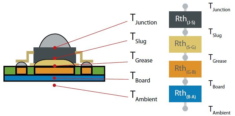
In principle, a power LED luminary can be seen as an electrical schema, and the main components are the LED chip itself, the module, the heat sink, and some kind of gap filler between the module and the heat sink, such as thermal grease or a thermal pad. Here, each part of the system has its own thermal resistance, which represents how much heat can be dissipated from each part. The thermal resistance of the entire system may be represented by the sum of the thermal resistance of the individual elements, which is equal to the temperature difference between the heat source and ambient divided by the amount of power dissipated.
Now, let me show an envelop-back calculation for heat dissipation that will allow you to make an informed choice about which heat sink to choose. As an example I take a (different) high-power COB LED model which has a maximum forward current of 900mA, with a plan to drive at a nominal forward current of 450mA at 36V. The maximum junction temperature (Tj) is 105°C but here I aim at a life time case temperature of 85°C (well below 90% of the maximum Tj). The estimated ambient temperature (Tamb) is 35°C. Note that running temperature of an LED is a key factor to life and a cause of early failure (many vendors suggest for maximum almost indefinite life the LED should not exceed 60°C).
- The electrical power (Pe) = 36V x 450mA = 16.2W
- The dissipated power (Pd) = 16.2W x 80% = 12.96W
- The temperature difference (dT) = 85°C – 35°C = 50°C
- The required maximal thermal resistance (Rth) of the LED heatsink plus the thermal interface material (thermal grease/pad) = dT / Pd = 50/12.96 = 3.85°C/W
Thermal resistance of the interface material is estimated as 0.2°C/W. So Rth heatsink = 3.85°C/W – 0.2°C/W = 3.65°C/W maximum. Any LED heatsink which does better than a lower thermal resistance value of 3.65°C/W in free air would make that the power LED case temperature will remain below the compelled 85°C. Acquired?
References